Eureka AIR delivers breakthrough ideas for toughest innovation challenges, trusted by R&D personnel around the world.

Three-level chopper apparatus

Active Publication Date: 2018-02-01
FUJI ELECTRIC CO LTD
View PDF0 Cites 5 Cited by
  • Summary
  • Abstract
  • Description
  • Claims
  • Application Information

AI Technical Summary

Benefits of technology

The present invention provides a three-level chopper apparatus that can prevent the charging voltage of a capacitor from becoming too high even if a failure occurs in a switch. This helps to improve the reliability and efficiency of the system.

Problems solved by technology

Thus, the capacitor corresponding to the other of the first and second switches is disadvantageously charged to a voltage higher than the voltage of the direct-current power supply so that an overvoltage occurs on the capacitor.

Method used


Image

  • Three-level chopper apparatus
  • Three-level chopper apparatus
  • Three-level chopper apparatus

Examples


first embodiment

[0055]The structure of a three-level chopper apparatus 100 according to a first embodiment is now described.

[0056](Structure of Three-Level Chopper Apparatus According to First Embodiment)

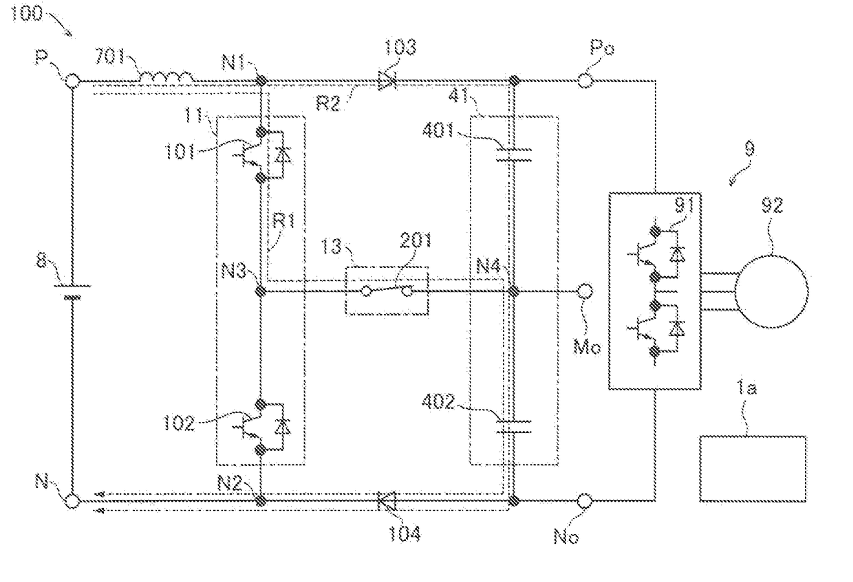
[0057]This three-level chopper apparatus 100 according to the first embodiment converts the voltage VE of a direct-current power supply 8 into direct-current voltages of three levels and outputs the direct-current voltages from a high potential output terminal Po, an intermediate potential output terminal Mo, and a low potential output terminal No, as shown in FIG. 1. The three-level chopper apparatus 100 is configured as a power converter used in the industrial field, the railway field, the power generation field, etc.

[0058]According to the first embodiment, the three-level chopper apparatus 100 includes the direct-current power supply 8, switches 101 and 102, diodes 103 and 104, capacitors 401 and 402, a chopper reactor 701 (hereinafter referred to as a “reactor 701”), a connection path 13, a pro...

second embodiment

[0089]A three-level chopper apparatus 200 according to a second embodiment is now described with reference to FIGS. 3 and 4.

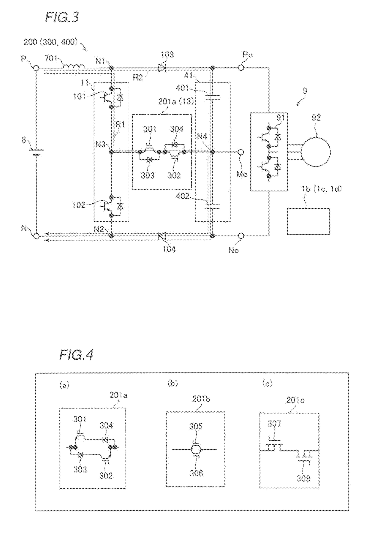
[0090]According to the second embodiment, the three-level chopper apparatus 200 includes a protection switch 201a that connects an intermediate point (connection point N3) of a switch series circuit 11 and an intermediate point (connection point N4) of a capacitor series circuit 41, as shown in FIG. 3.

[0091]According to the second embodiment, the protection switch 201a is configured as a bidirectional protection switch connected in series to a connection path 13. The protection switch 201a is an example of a “protection switch circuit” or a “bidirectional protection switch” in the claims.

[0092]For example, the protection switch 201a includes two IGBTs (insulated gate bipolar transistors) 301 and 302 connected in anti-parallel with diodes 303 and 304, respectively, as shown in FIG. 3. These IGBTs 301 and 302 are connected in anti-series to each other. In other w...

third embodiment

[0112]A three-level chopper apparatus 300 according to a third embodiment is now described with reference to FIG. 3 and view (b) of FIG. 4.

[0113]According to the third embodiment, the three-level chopper apparatus 300 includes a protection switch 201b inserted into a connection path 13 that connects an intermediate point (connection point N3) of a switch series circuit 11 and an intermediate point (connection point N4) of a capacitor series circuit 41 and a control circuit 1c (see FIG. 3), as shown in view (b) of FIG. 4.

[0114]According to the third embodiment, the protection switch 201b is constructed by connecting two reverse blocking IGBTs 305 and 306 in anti-parallel to each other. The control circuit 1c serves as a short circuit detector. The control circuit 1c detects the short circuit failure of a switch 101 when the switch 101 has a short circuit failure, and performs control for turning off a gate of the reverse blocking IGBT 306 of the protection switch 201b to disconnect t...


PUM


Abstract

A three-level chopper apparatus includes a protection switch circuit that changes a current pathway through which an overvoltage is applied to a second capacitor or a first capacitor to a current pathway through which no overvoltage is applied to the second capacitor or the first capacitor when a first switch or a second switch has a failure.

Description

CROSS-REFERENCE TO RELATED APPLICATION[0001]The priority application number JP2016-150227, Three-Level Chopper Apparatus, Jul. 29, 2016, Motoyoshi Kubouchi and Yasushi Abe, upon which this patent application is based, is hereby incorporated by reference.BACKGROUND OF THE INVENTIONField of the Invention[0002]The present invention relates to a three-level chopper apparatus, and more particularly, it relates to a three-level chopper apparatus including a first capacitor and a second capacitor connected in series to each other.Description of the Background Art[0003]A three-level chopper apparatus including a first capacitor and a second capacitor connected in series to each other is known in general, as disclosed in Japanese Patent Laying-Open No. 9-135589.[0004]Japanese Patent Laying-Open No. 9-135589 discloses a speed controller for an induction motor that includes a direct-current power supply, a reactor, first and second switches including transistors or the like, first and second c...

Claims


Application Information

Patent Timeline
IPC IPC(8): H02M1/32H02M1/14H02M3/158
CPCH02M1/32H02M3/158H02P27/06H02M2001/325H02M7/537H02M1/14H02M7/483H02M1/36H02M1/325
Inventor KUBOUCHI, MOTOYOSHIABE, YASUSHI
Owner FUJI ELECTRIC CO LTD
Why Eureka
Eureka Blog
Learn More