Golf club head cover

Inactive Publication Date: 2018-02-22
HEILY JOHN PATRICK
8 Cites 0 Cited by

AI-Extracted Technical Summary

Problems solved by technology

Likewise, during transport the clubs may bump against other objects, potentially causing damage or at least generating an annoying clanging sound.
The cloth-type cover works reasonably well to dampen noise and protect against minor impacts, but works less well for a more significant shock.
The cloth head cover is also typically created with an extension that covers the hozzle and a portion of the shaft, creating a snug fit that can pose a challenge to attach to or remove from the club.
Some have tried to create a more rigid or clamshell ...

Benefits of technology

[0015]The golf club head cover preferably includes a mounting plate attached to...

Abstract

A golf club head cover is formed from rigid or semi-rigid materials and is divided in two halves as a clamshell. The head cover includes a head covering portion and a shaft covering portion. A clip is attached to a sole region of the head cover, between the toe and the heel, to allow a user to open or close the head cover as desired.

Application Domain

Golfing accessoriesRacket sports

Technology Topic

Golf clubHead parts +2

Image

  • Golf club head cover
  • Golf club head cover
  • Golf club head cover

Examples

  • Experimental program(1)

Example

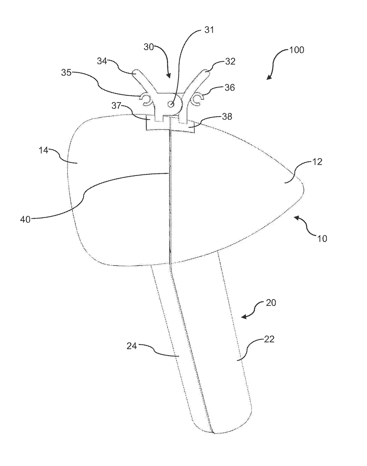
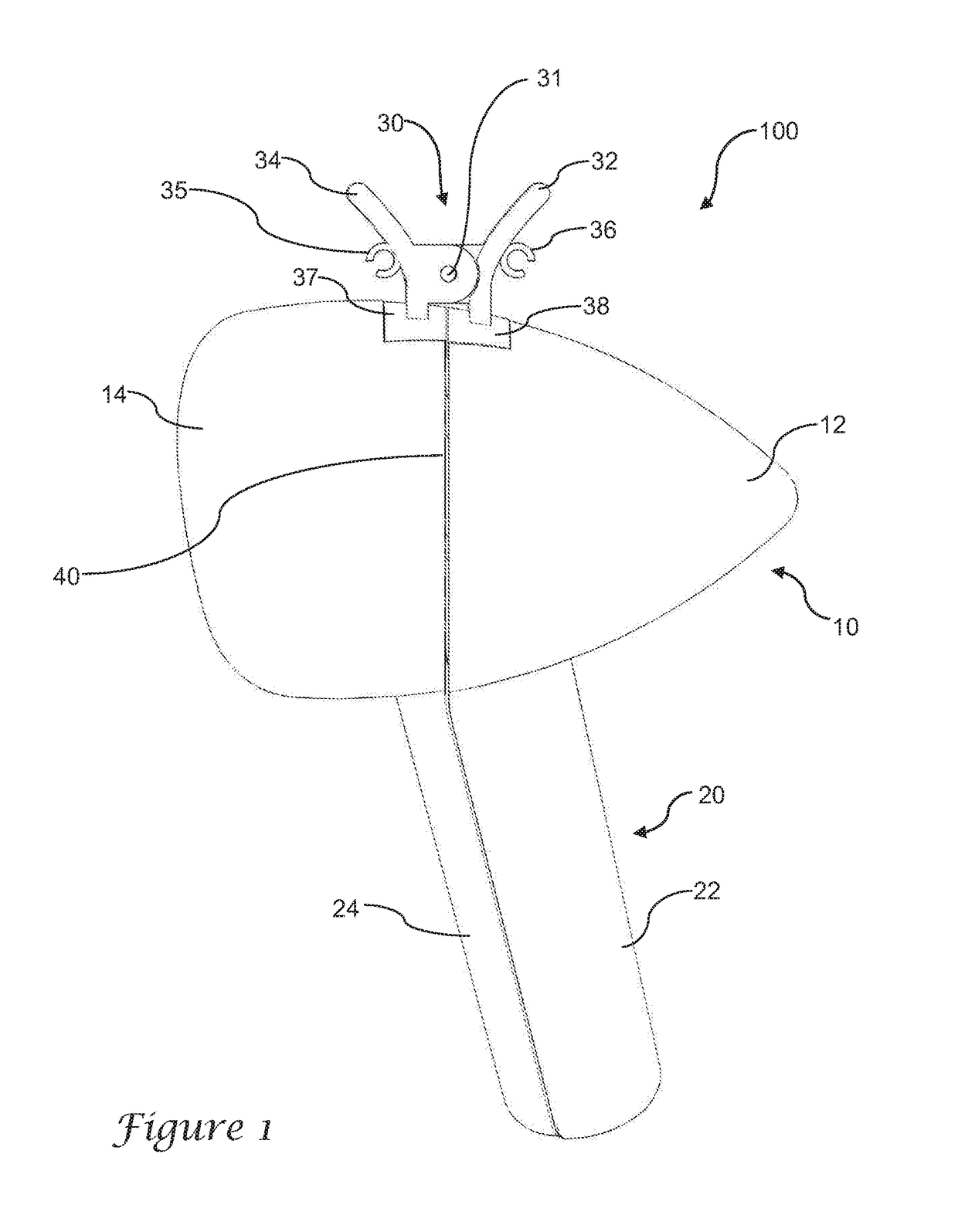
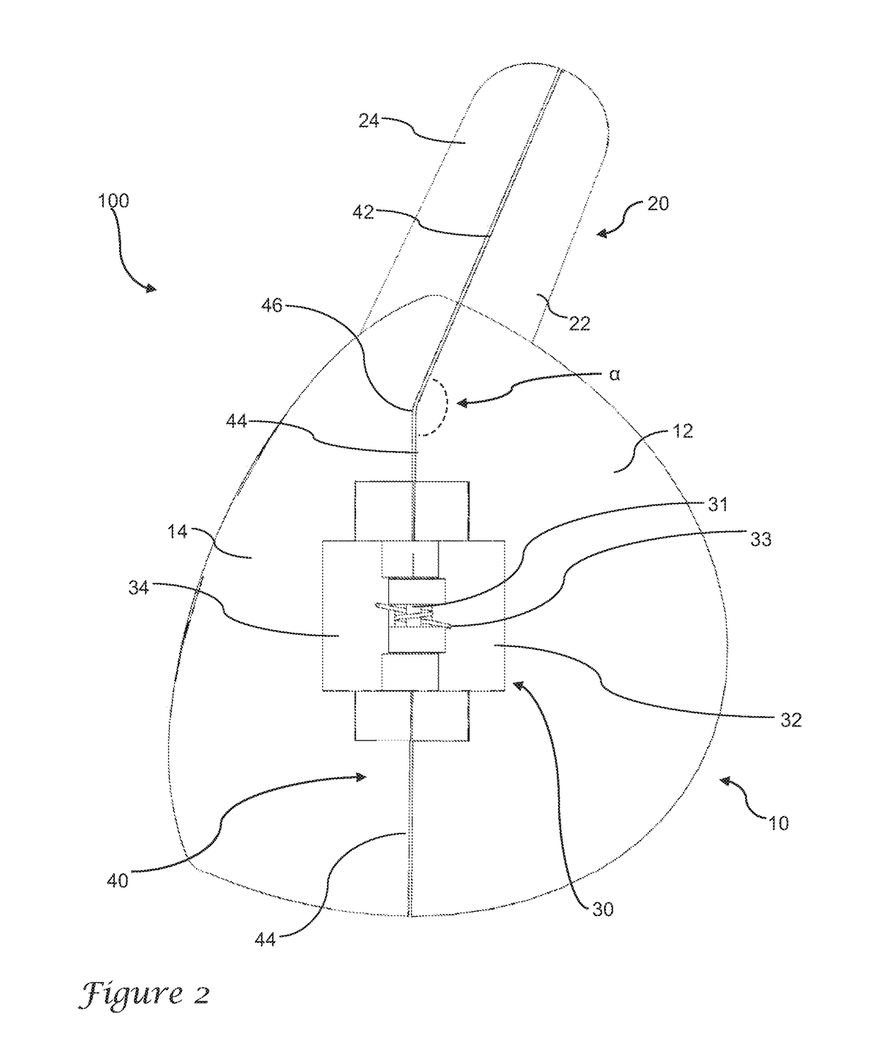
[0026]A preferred golf club head cover 100 is shown in a front view in FIG. 1. In a preferred version, the head cover 100 is formed with a clamshell configuration having a first half and a second half separated by a seam 40. The first half includes a first head covering portion 12 and a first shaft covering portion 22, and in the illustrated example the first head covering portion and the first shaft covering portion are integrally formed from a single material. In one version, each of the first half and the second half are formed from a castable flexible urethane foam. In other versions, it may be made from other more rigid plastic materials, or other resilient materials such as silicone. Most preferably, the particular version of foam is rated as a semi-rigid material such that it will not collapse under its own weight. The second half likewise includes a second head covering portion 14 and a second shaft covering portion 24, preferably integrally formed from a common material.
[0027]The first and second halves are separable from one another but joined along the seam 40 such that the first and second halves form an enclosed interior volume when they abut one another along the seam. The head covering portions define a bulbous shape configured to cover a golf club, preferably a driver or fairway wood. The shaft covering portions define an elongated tube shape configured to cover a portion of a golf club shaft.
[0028]Most preferably, the interface along the seam creates close contact and a snug fit along the entire seam, such that there are no gaps or openings other than at a distal end 60, as shown in FIG. 3. The opening at the distal end allows the club shaft to extend through the opening when the club head is stored within the club cover. In the illustrated example, each half terminates in a planar rim that abuts the opposing planar rim of the other half. In other versions, the first and second halves may form a mating interface such as a tongue and groove arrangement (with a tongue formed on one of the first or second half, and a groove formed on the other of the first and second half), or other abutment features to ensure that the rim of each half properly aligns with the opposing rim and remains in alignment.
[0029]In the illustrated example, the first and second halves are biased toward one another and can be pivoted away from one another through the use of a top-mounted hinge 30. In one version, the hinge is configured as a butterfly clip having a first wing or handle 32 and a second wing or handle 34 joined at a pivot location 31 by a pin or axle. The first wing is mounted to the first head covering portion 12, preferably through a mounting plate 38. The wing and mounting plate may be integrally formed, or the wing may be separately constructed and attached to the mounting plate. In one version, the wing and mounting plate are both formed from aluminum to provide lightweight strength and rigidity. In other versions either component may be formed from other metals or yet other materials such as plastics, though preferably both components are formed from a material that is rigid when in use. A second wing 34 is similarly attached to a second mounting plate 37, attached to the second head covering portion 14, and preferably made from the same materials as with the first wing and first mounting plate.
[0030]In some versions, the head cover may include one or more tee holders 35, 36. As seen in FIG. 1, the tee holders may be attached to outer faces of the first wing 32 and second wing 34. Each may be formed as a C-shaped clip for receiving a golf tee, as best seen in FIG. 4. In some versions the tee holders may be enclosed rings or holes rather than C-shaped with an outer opening. In yet other versions, one or more tee holders may be mounted on either of the head covering portions or shaft covering portions.
[0031]FIG. 2 illustrates a top view of a preferred golf club head cover, including hinge or clip 30 joining the first half (with first head covering portion 12 and first shaft covering portion 22) to the second half (with second head covering portion 14 and second shaft covering portion 24). In this top view, the pin 31 is visible, which carries a coil spring 33 having opposing ends that press against the first and second wings 32, 34 in order to urge them into the closed position.
[0032]As best seen in FIG. 2, the seam 40 is preferably formed so that it does not lie in a single plane. Rather, the seam is formed so that it follows two planes, so that in the illustrated version there is a first seam segment 42 and a second seam segment 44. The first seam segment 42 divides the shaft covering portion 20, and extends along a first plane and at least partly into the golf head covering portion 10 before diverging along a second plane illustrated by the seam line 44 which divides the majority of the head covering portion 10. The first seam segment 42 and second seam segment 44 are transverse to one another and meet at an apex 46 positioned at a heel 15 of the head covering portion, opposite a toe portion 16, best seen in FIG. 3. The intersection of the first seam segment and second seam segment at the apex 46 defines an angle α, and in the illustrated example the angle is less than 180 degrees and greater than 135 degrees. More preferably, the angle is between 145 and 175 degrees.
[0033]FIGS. 5-7 illustrate a preferred golf club head cover in an open position, in which the opposing wings or handles of the spring clip 30 are urged toward one another in order to pry the two halves apart from one another in order to insert or release a golf club from the cover. Most preferably, the clip 30 is biased to urge the first and second halves toward another in the resting position, requiring the application of a force to separate the two halves along the seam.
[0034]Each of the first half and the second half is formed as a portion of a shell, defining an interior cavity that includes a golf head cavity (e.g., 64 in FIG. 7) and a golf shaft cavity (e.g., 62 in FIG. 7). Though a cavity for the first half is illustrated in FIG. 7, the cavity in the second half is similarly arranged so that the first and second halves define an interior volume when pivoted toward one another along the seam. As illustrated, the seam dividing the first half and the second half creates two halves of substantially equal volume. The two halves are not identically shaped, and therefore the volumes may not be perfectly equal, but in the context of this invention “substantially equal volume” means that each half defines at least 40% of the total volume of the head cover.
[0035]One advantage of the illustrated invention is that the clip 30 is placed at an upper region of the head cover, with reference to the orientation of the head cover when attached to a golf club and positioned in a golf bag. The preferred orientation is best seen with respect to FIG. 3. In the case of a typical golf bag which is resting on a horizontal ground surface represented by plane H in FIG. 3, the golf bag may be inclined at an angle and resting on the legs of the bag in a tripod configuration. In such a case, the clubs are typically inclined along an angle with respect to the horizontal represented by axis S in FIG. 3. As illustrated, the axis S extends centrally through the shaft covering portion 20, forming an angle θ with respect to the horizontal. Most preferably, the angle θ is in the range of 35 to 60 degrees, and more preferably about 45 degrees. A tangent line T1 through the top of the golf club cover (when in the orientation of FIG. 3) is substantially parallel to the horizontal. A second line T2 generally defines the region of the head covering portion (that is, between T1 and T2) that surrounds the sole of a golf club (such as a driver, or fairway wood) when in position within the cover. In a preferred version, the clip 30 is positioned along the tangent line (or plane), and most preferably the clip 30 is positioned along the distal end defining a sole region 70 (opposite the proximal end 72) of the club cover, in which the sole region is the region between planes T1 and T2. As noted above, the distal end of the club cover is not at the toe 16, nor at the heel 15, but rather positioned centrally between the heel and the toe.
[0036]In the orientation as described above, the clip should be positioned for grasping in the manner illustrated in FIG. 3, so that the clip is substantially at the top of the golf club head cover as it rests in the golf bag. This position allows the club head cover to be grasped by a user by squeezing the clip 30 to both lift the cover and open the two halves at substantially the same time. Consequently, a single-handed removal technique is possible, allowing the cover to be opened and removed with one hand while reaching for the club itself with the other hand. The vertical orientation similarly allows the user to grip the clip and raise the club out of the bag to any distance needed, and then to squeeze the clip to separate the two halves once the cover is clear of the other clubs in the bag.
[0037]While the preferred embodiment of the invention has been illustrated and described, as noted above, many changes can be made without departing from the spirit and scope of the invention. Accordingly, the scope of the invention is not limited by the disclosure of the preferred embodiment. Instead, the invention should be determined entirely by reference to the claims that follow.

PUM

no PUM

Description & Claims & Application Information

We can also present the details of the Description, Claims and Application information to help users get a comprehensive understanding of the technical details of the patent, such as background art, summary of invention, brief description of drawings, description of embodiments, and other original content. On the other hand, users can also determine the specific scope of protection of the technology through the list of claims; as well as understand the changes in the life cycle of the technology with the presentation of the patent timeline. Login to view more.
Why Eureka
Try Eureka