Suspended spindle assembly for recumbent tricyles

a spindle assembly and recumbent technology, applied in the direction of cycle equipment, steering devices, cycle equipment, etc., can solve the problems of hand and arm fatigue, overall rider discomfort, etc., and achieve the effect of improving trike handling and rider comfort, and reducing rider fatigu

Active Publication Date: 2018-02-22
BIG CAT HUMAN POWERED VEHICLES
View PDF0 Cites 0 Cited by
  • Summary
  • Abstract
  • Description
  • Claims
  • Application Information

AI Technical Summary

Benefits of technology

[0004]This invention is directed to a suspended spindle assembly for each of the front wheels of recumbent tric

Problems solved by technology

This can create fatigue of the hands and arms while opera

Method used


Image

  • Suspended spindle assembly for recumbent tricyles
  • Suspended spindle assembly for recumbent tricyles
  • Suspended spindle assembly for recumbent tricyles

Examples


Embodiment Construction

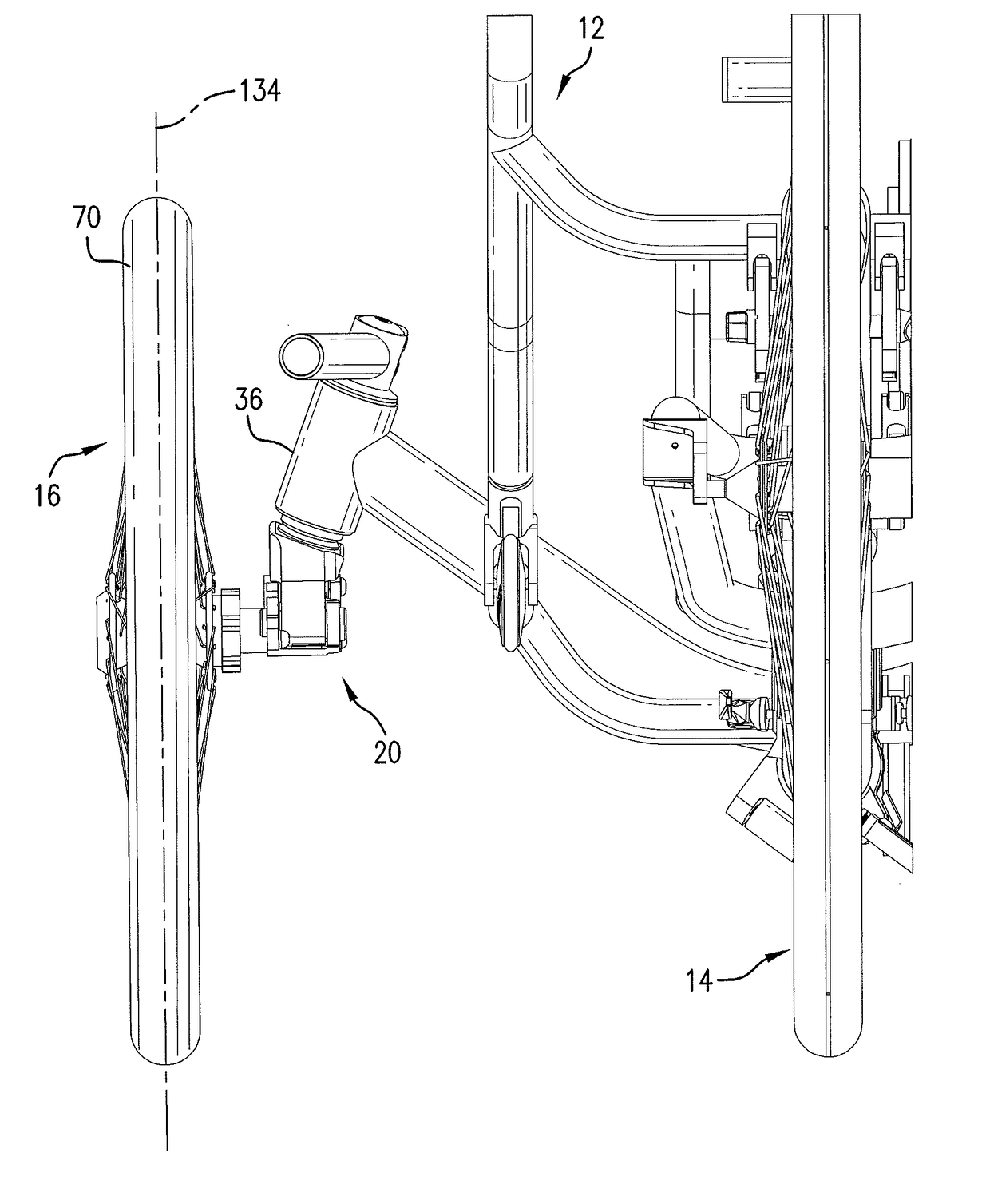
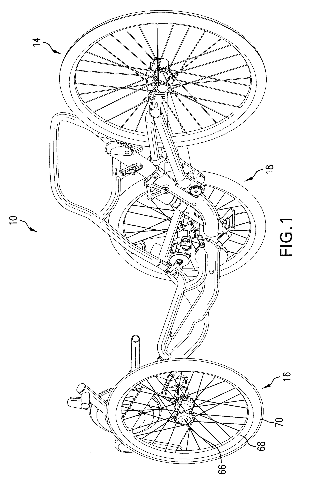
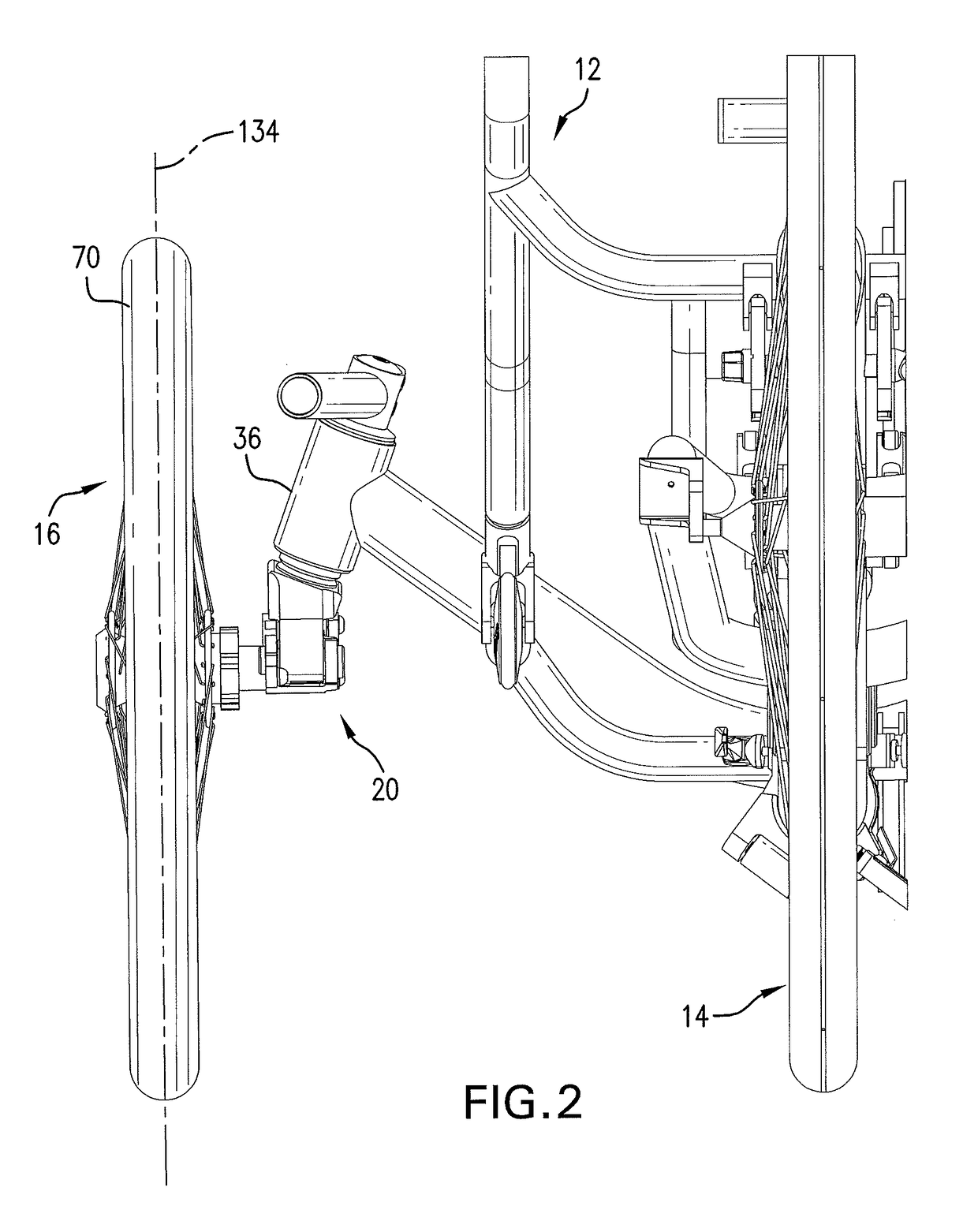
[0018]Referring initially to FIGS. 1 and 2, a recumbent tricycle 10 is illustrated which comprises a frame 12 coupled to a rear wheel assembly 14 and two front wheel assemblies 16, 18. Details of the construction of the tricycle 10 form no part of this invention and are therefore not described herein. For purposes of the present discussion, the term “rearward” refers to a direction toward the rear wheel assembly 14 and “forward” denotes the opposite direction toward the front wheel assemblies 16, 18. Additionally, “upward,”“downward,”“upper” and “lower” denote spatial orientations of the tricycle 10 relative to a ground surface on which it rests when in use.

[0019]This invention is directed to a suspended spindle assembly 20, one of which is connected to each of the front wheel assemblies 16, 18. The two spindle assemblies 20 are identical in structure and function, and therefore only one of which is described in the discussion which follows.

[0020]Referring now to FIG. 3, the spindle...


PUM


Abstract

A suspended spindle assembly is disclosed for each of the front wheels of recumbent tricycles which absorb vibration and bumps to reduce rider fatigue while improving trike handling and rider comfort.

Description

FIELD OF THE INVENTION[0001]This invention relates to spindle assemblies, and, more particularly, to a suspended spindle assembly for use in recumbent tricycles.BACKGROUND OF THE INVENTION[0002]Tadpole recumbent tricycles generally comprises a frame coupled to a single rear wheel and two smaller front wheels with a seat located between them. Each front wheel is joined to the frame by a spindle assembly connected between the axle of the wheel and the head tube of the frame. The spindle assemblies function to couple the front wheels to the handlebars and steering mechanism of the recumbent tricycle.[0003]Typically, recumbent tricycles have no structure for absorbing vibration and / or shock resulting from engagement of the wheels with the road surface and with any bumps or other obstacles that may be encountered while riding. Conventional spindle assemblies are rigidly connected between each front wheel and the frame such that the rider feels essentially everything that the wheels conta...

Claims


Application Information

Patent Timeline
IPC IPC(8): B62K25/00B62K21/08B60G3/28B62K3/00
CPCB62K25/00B62K21/08B60G3/285B62K3/005B62K5/05B60G2200/10B62K2005/001B60G2206/50B62K5/02B60G2300/122
Inventor CAMASMIE, PAULOCALLA, JUSTIN
Owner BIG CAT HUMAN POWERED VEHICLES
Why Eureka
Try Eureka