Stand selectively usable as a monopod or a tripod

a technology of monopods and stands, applied in the direction of stands/trestles, instruments, camera body details, etc., can solve the problems of unsuitable flat surfaces in a particular location, unfavorable tripods, and inability to move quickly and easily from one location to another,

Inactive Publication Date: 2018-03-22
DENNY MFG CO INC A CORP OF AL
View PDF0 Cites 29 Cited by
  • Summary
  • Abstract
  • Description
  • Claims
  • Application Information

AI Technical Summary

Benefits of technology

[0006]There is therefore a need in the art for an improved equipment stand that will provide a stable platform for supporting a camera or lighting equipment and that can offer hand's free operation if desired but which will also allow the photographer to rapidly change shooting angles if desired or required.
[0008]The stand disclosed herein may further be useful for a photographer or videographer who typically uses a monopod for mobility and ease of use but who would appreciate being able to have a break from holding their equipment when not actively working or while adjusting their equipment.
[0009]Instead of having to use two separate stands, the presently disclosed stand allows the photographer or videographer to use a single stand that may be quickly and easily converted between a monopod and a tripod. The presently disclosed stand offers the photographer or videographer the advantage of not having to continuously hold on to a monopod because he or she can simply disengage a retaining device provided on the stand and then place the stand on a support surface. A leg assembly on the stand will automatically open up and move to a tripod position when the stand is placed onto the support surface. When the photographer wishes to move, he or she will simply pick up the stand and the leg assembly will automatically close. If the stand is to be used as a tripod, it is simply placed on the support surface in the new location. If the stand is to be used as a monopod in the new location, the retaining device is re-engaged to lock the leg assembly in the closed position.

Problems solved by technology

In many instances, however, suitable flat surfaces may not be available in a particular location.
The freedom to move quickly and easily from one location to another is not possible with tripods as the entire tripod has to be lifted off the ground and repositioned.
Tripods can be quite bulky and heavy.
Additionally, the locked and spread apart legs tend to make the device unwieldy and difficult to maneuver around objects.
Consequently, the photographer will frequently have to disengage and collapse individual legs to move a tripod from one location to another.
Monopods, because they only have a single leg, tend to be unstable and cannot stand on a support surface on their own.
However, if the photographer has to work for a sustained period of time, continuously holding on to the monopod or the camera, this can become extremely tiring.
It is also difficult for the photographer to make adjustments to their equipment without laying the stand and the equipment down on the support surface or without disengaging their equipment from the monopod.
However, both of these devices are fairly cumbersome and, consequently, a photographer may opt to carry only one of these two types of stands to a shoot.

Method used


Image

  • Stand selectively usable as a monopod or a tripod
  • Stand selectively usable as a monopod or a tripod
  • Stand selectively usable as a monopod or a tripod

Examples


Embodiment Construction

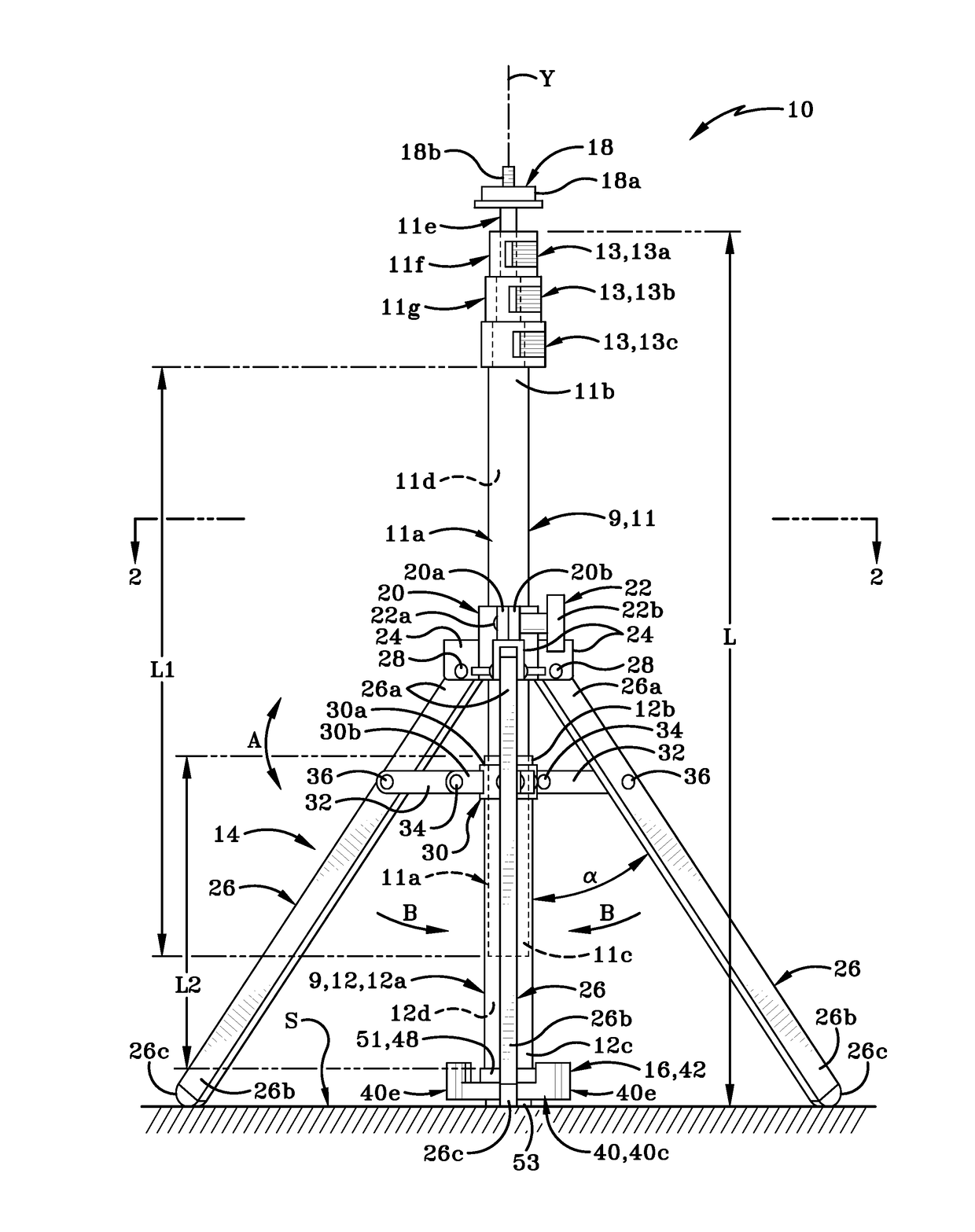
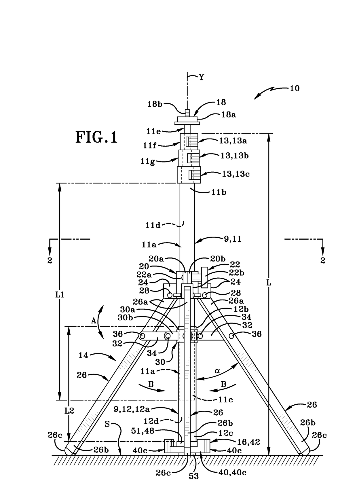
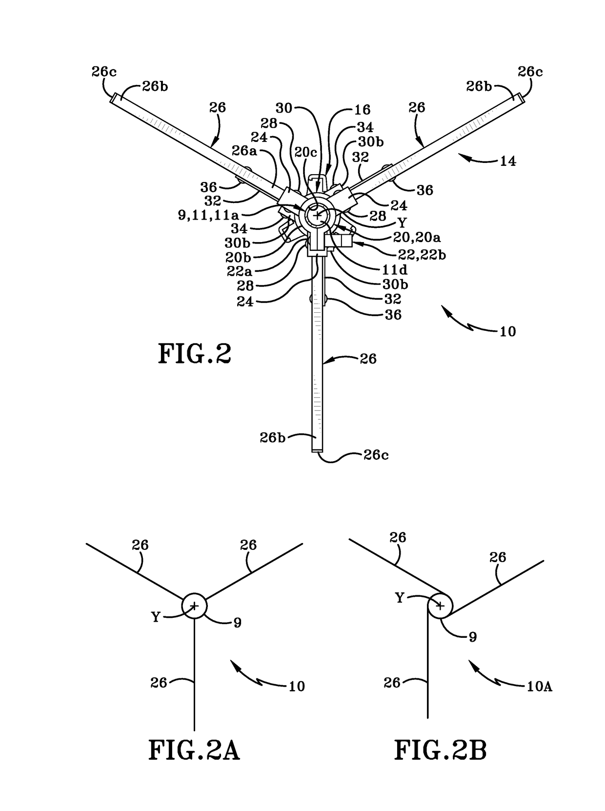
[0039]Referring to FIGS. 1-9, there is shown a stand for supporting equipment, such as camera equipment, video equipment or lighting equipment, for instance. The stand in accordance with an aspect of the present invention is generally indicated at 10. Stand 10 is selectively movable between a first position (FIG. 1) where stand 10 is usable as a tripod and a second position (FIG. 9) where stand 10 is usable as a monopod. Stand 10 may comprise a shaft 9, a leg assembly 14 and a retaining device 16.

[0040]Shaft 9 may comprise an elongate tubular member made up of an upper tubular member 11 and a lower tubular member 12. Upper tubular member 11 may comprise a peripheral wall 11a having an upper end 11b, a lower end 11c, and defining a bore 11d that extends between upper end 11b and lower end 11c. Upper tubular member 11 may also comprise a first section 11e; a second section 11f and a third section 11g. First, second and third sections 11e, 11f and 11g may be telescopingly engaged with ...


PUM


Abstract

A dual-purpose stand and method for supporting photographic equipment is disclosed. The stand is able to be used as a monopod or a tripod. A retaining device is provided on the stand. The retaining device is selectively engaged to lock a leg assembly provided on the stand in a collapsed or closed position when the stand is to be used as a monopod. The retaining device is disengaged when the stand is to be used as a tripod. When the retaining device is disengaged, the stand will automatically become a tripod when placed on a support surface. The stand's legs will automatically move to an extended or open position when the stand is set down on the support surface and the legs will automatically move back to a collapsed or closed position when the stand is lifted from the support surface.

Description

CROSS REFERENCE TO RELATED APPLICATIONS[0001]This application claims the benefit of U.S. Provisional Application Ser. No. 62 / 495,507, filed on Sep. 16, 2016, the entire disclosure of which is incorporated herein by reference.BACKGROUND OF THE INVENTIONTechnical Field[0002]The present invention is directed generally to photographic equipment. More particularly, the present invention relates to a stand for supporting equipment such as a camera or a light in a stable position during use. Specifically, the present invention is a dual-purpose stand that is able to be used as a monopod or as a tripod. The stand includes a retaining device that is selectively engaged to lock the stand in a monopod position and is selectively disengaged to allow the stand to be used as a tripod. After disengagement of the retaining device the stand's legs will automatically open to the tripod position when the stand is set down on a support surface and the legs will automatically close when the stand is lif...

Claims


Application Information

Patent Timeline
Patent Type & Authority Applications(United States)
IPC IPC(8): F16M11/34F16M11/30F16M11/20F16M11/04
CPCF16M11/34F16M11/30G03B17/561F16M11/04F16M11/2014F16M11/046F16M11/08F16M11/28F16M13/00
Inventor BOSNAKOVIC, FREDERICK
Owner DENNY MFG CO INC A CORP OF AL
Why Eureka
Try Eureka