Bypass connector for a socket assembly

a technology of socket assembly and bypass connector, which is applied in the direction of electrically conductive connections, coupling device connections, instruments, etc., can solve the problems of delay or problem, not particularly economical, and the lugs are not readily removable, so as to reduce the number of socket configurations, improve the bypass system, and be convenient to configur

Active Publication Date: 2005-12-22
EATON INTELLIGENT POWER LIMITED
View PDF23 Cites 2 Cited by
  • Summary
  • Abstract
  • Description
  • Claims
  • Application Information

AI Technical Summary

Benefits of technology

[0004] Among the several objects of this invention may be noted the provision of meter socket assembly having an improved meter bypass system; the provision of such a socket assembly which can be manufactured with lugs of a single standard configuration, regardless of whether the socket assembly has a bypass system, thereby reducing the number of socket configurations which need to be stocked; the provision of such a socket assembly which can be readily configured in the field and / or at the factory to include or eliminate the bypass system; the provision of such a socket assembly which can be quickly and easily converted between an assembly with the bypass feature and an assembly without the bypass feature; and the provision of a meter socket assembly system which includes a standard meter socket assembly and two types of connectors, one type with a bypass horn for attachment to the lugs to provide a socket assembly with a bypass feature and one without a bypass horn for attachment to the lugs to provide a socket assembly without a bypass feature.

Problems solved by technology

Because the lugs are not readily removable in the field, manufacturers typically stock two types of meter socket assemblies, one with lugs having the bypass component and one with lugs without the bypass component.
This arrangement is not particularly economical and may cause delays or problems in the field if the desired configuration is not available.

Method used


Image

  • Bypass connector for a socket assembly
  • Bypass connector for a socket assembly
  • Bypass connector for a socket assembly

Examples


Embodiment Construction

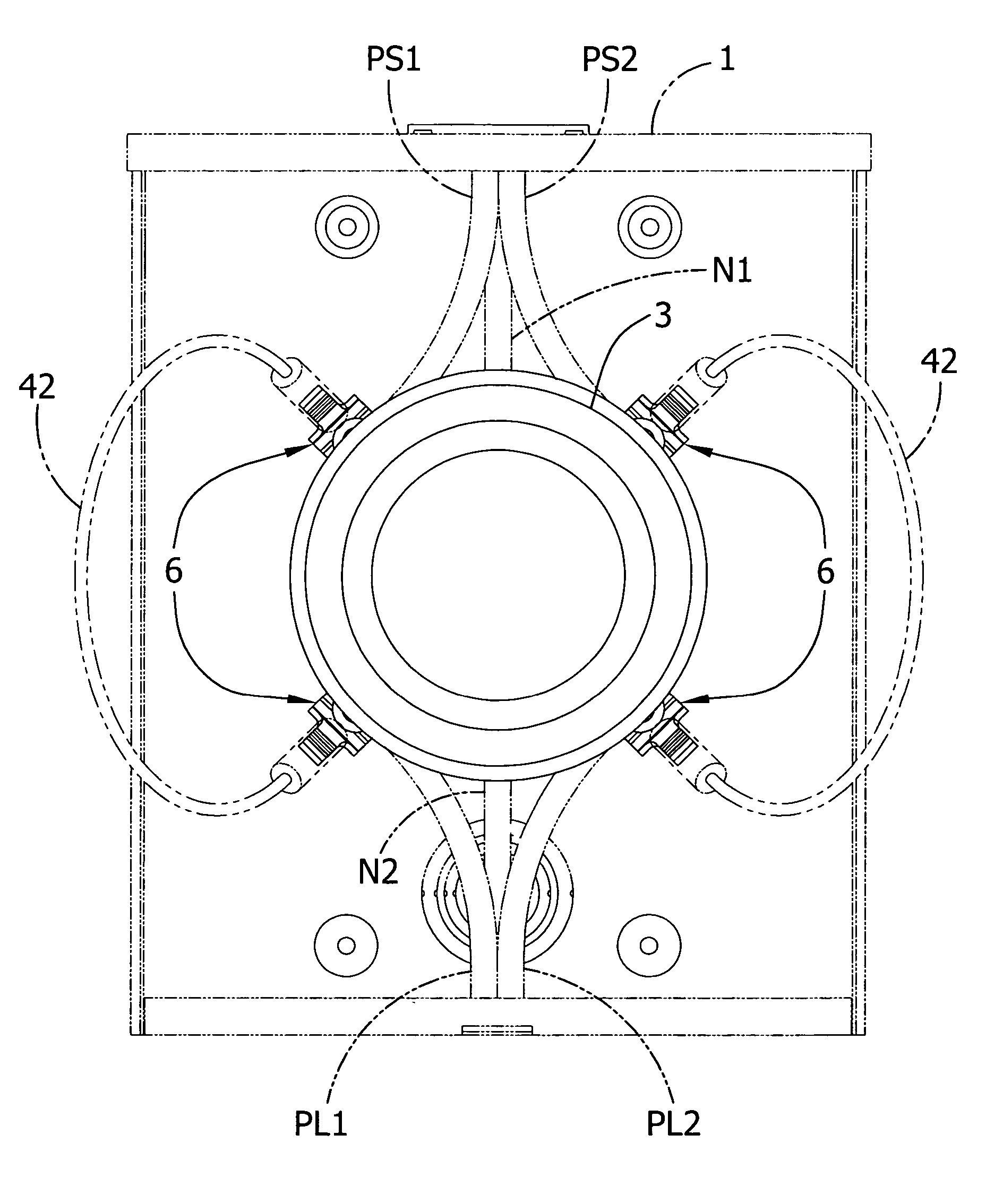
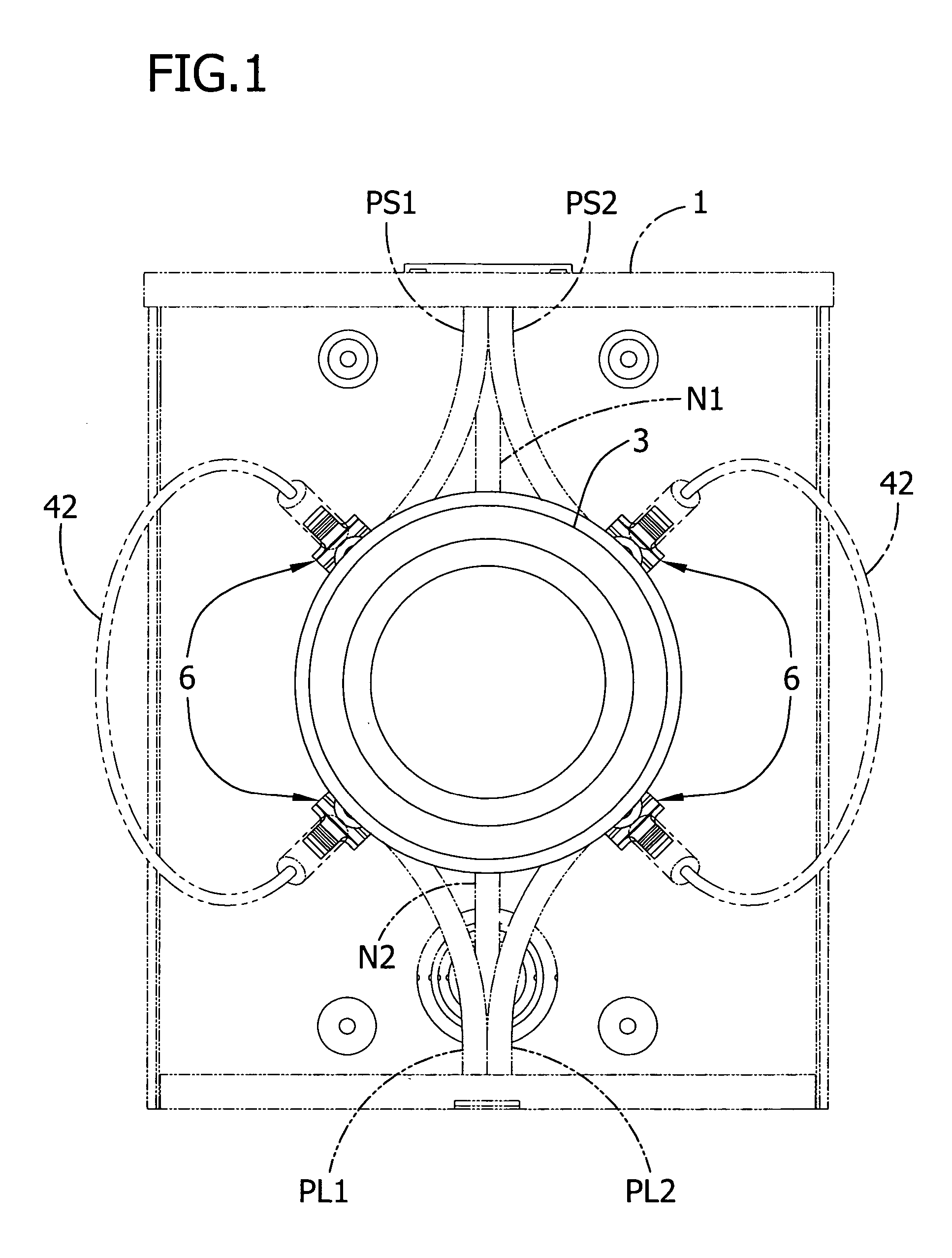
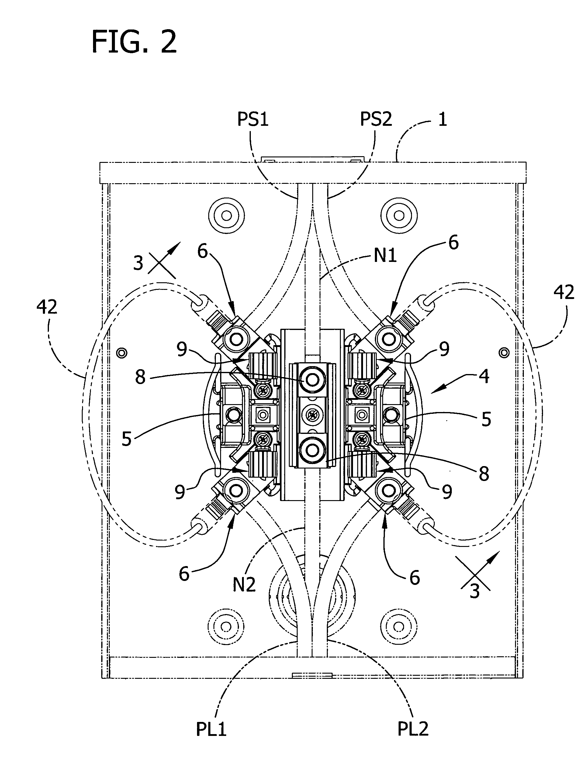
[0020] Referring now to the drawings, FIG. 1 shows an enclosure 1 (sometimes referred to as a meter box) for an electric meter 3. A meter socket assembly, generally designated 4, is mounted in the meter box 1 and comprises a support 5 bolted to the back wall of the box. The socket assembly 4 includes a plurality of power line connector subassemblies, generally designated 6, secured to the support 5 for connection to electric power conductors of a power line system. The particular installation shown in FIGS. 1 and 2 is a single-phase, 3-wire system comprising two power supply lines PS1, PS2 which transmit power from a suitable source of power and are connected to two corresponding connector subassemblies 6, two power load lines PL1, PL2 which transmit power to the facility being serviced and are connected to two corresponding connector subassemblies 6, and two neutral lines N1, N2 connected to neutral connectors 8 secured centrally of the support 5. A plurality of socket connectors 9...


PUM


Abstract

A socket assembly for mounting an electric meter comprising a plurality of power line connector subassemblies for connecting electric power lines to the socket assembly. Each subassembly comprises a generally U-shaped lug of electrically conductive material defining a saddle for supporting one of the electric power lines, a connector and a screw. The connector comprises a body of electrically conductive material having opposite sides slidably engageable with respective legs of the lug. A horn of electrically conductive material projects from the body for connection to a bypass conductor forming at least part of an electrical path for bypassing the electric meter. The screw is threadable through a screw opening in the connector to a position in which the screw is adapted to contact said power line in the saddle of the lug.

Description

BACKGROUND OF THE INVENTION [0001] This invention relates generally to electric meters for monitoring the consumption of electricity, and more particularly to components used in a meter box to provide an electrical path which bypasses the meter. [0002] A meter box typically houses a socket assembly and an electric meter which plugs into the socket assembly. A conventional socket assembly includes a base and a number of connector subassemblies mounted on the base for connection of the incoming power supply lines and outgoing power load lines. A first version of a connector subassembly includes a U-shaped lug, a nut-type connector having a sliding connection with the lug, and a screw threaded through an opening in the nut-type connector into pressure contact with a power conductor positioned in the lug. A second version of the subassembly is identical to the first except that the lug is equipped with a component (e.g., a tang-like member or “horn”) which can be used to bypass the mete...

Claims


Application Information

Patent Timeline
Patent Type & Authority Applications(United States)
IPC IPC(8): G01R11/04G01R17/10H02B1/00
CPCY10S439/957G01R11/04
Inventor WITHERBEE, MARTIN L.CRINER, BRAD A.KELLERMAN, DALLAS WAYNE
Owner EATON INTELLIGENT POWER LIMITED
Why Eureka
Try Eureka