Electronic oven with infrared evaluative control

a technology of infrared evaluative control and electronic oven, which is applied in the direction of program control, domestic stoves or ranges, instruments, etc., can solve problems such as constraints in the real world, and achieve the effects of improving the operation of electronic ovens, enhancing the accuracy and efficiency of control systems, and more reliable heating

Active Publication Date: 2018-04-05
THE MARKOV CORP
View PDF3 Cites 22 Cited by
  • Summary
  • Abstract
  • Description
  • Claims
  • Application Information

AI Technical Summary

Benefits of technology

[0017]Some of the approaches disclosed herein involve an alteration to a control or training system based on the identity of the item placed in the chamber or a particular kind of heating selected by a user. In particular, the action-value function, cost function, heuristic, extrapolation engine, deviation detector, state characteristics, reward derivation procedure, optimization analysis, or training system for a reinforcement learning approach mentioned herein could be altered based on the identity of the item or commands from the user. For example, the cost function and reward derivation procedure could both be altered if an item was known to recovery slowly from major temperature disparities such that keeping an even temperature was associated with greater rewards and lower costs. As another example, the tolerance for the optimization analysis could be decreased if the item was recognized as one that dried out rapidly or charred if a target temperature was exceeded for a short period of time.
[0018]In these approaches, information concerning the identity of the item can be provided by various channels to assist the operation of the control and training systems. The channels can include a QR code or UPC barcode located on a package of the item. Another channel could be a response to the item to a given calibration step such as a monitored response of the item to an application of energy as monitored by an infrared sensor. Another channel could be a separate machine learning algorithm such as a traditional neural network trained to work as a classification system to identify items in the chamber as specific food items. Another channel could be the visible light reflected off the item and detected by a visible light sensor. Another channel could be an input from a user of the electronic oven via a user interface. The information provided via these channels could simply identify the item and allow the controls system to determine how to alter itself, or the information could actually be directly applied to change the control system. For example, a QR code could identify an item as a frozen dinner, and the control system could load a new reward derivation procedure based on the identification information, or the information in the QR could itself be a new reward derivation procedure. For example, the reward derivation procedure could reward a gradual phase change in the item from frozen to melted.
[0020]The disclosed approaches improve the fields of electronic ovens and microwave heating by providing more reliable heating. Controlling the application of electromagnetic energy to an item in a controlled and reliable manner is a technical problem. The disclosed approaches include a set of aspects that contribute to a solution to that technical problem. In particular, the use of evaluative feedback, optimization analyses, deterministic planners, and reinforcement learning as described herein each enhance the accuracy and efficiency of a control system for heating an item in an electronic oven in an inventive manner to solve the aforementioned technical problem and improve the operation of electronic ovens generally.

Problems solved by technology

However, training a control system using a training environment that includes physical reactions taking place in the real world involves constraints set by the actual speed of those physical reactions.

Method used


Image

  • Electronic oven with infrared evaluative control
  • Electronic oven with infrared evaluative control
  • Electronic oven with infrared evaluative control

Examples


Embodiment Construction

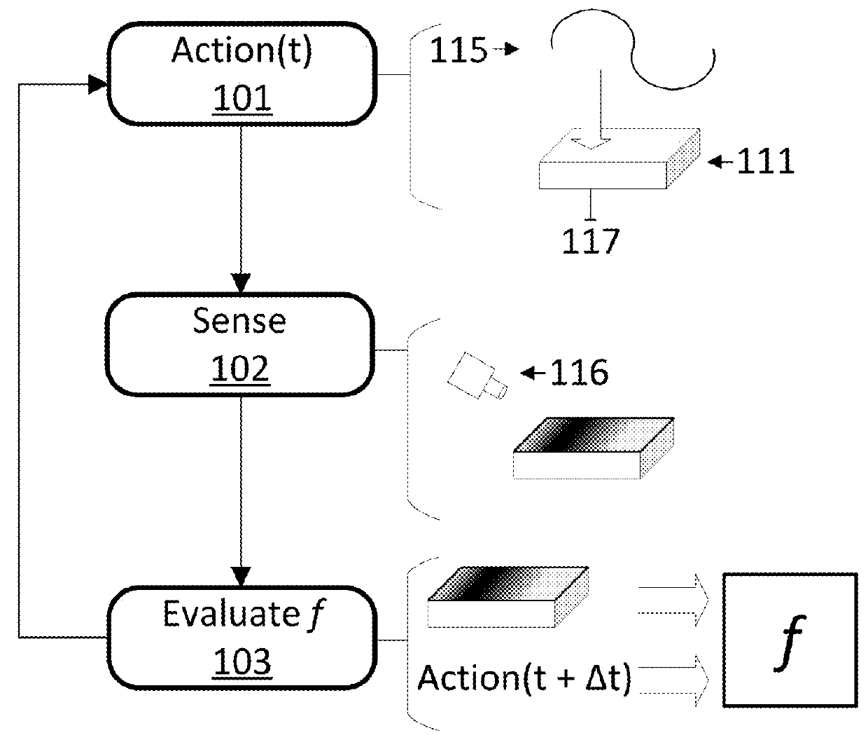
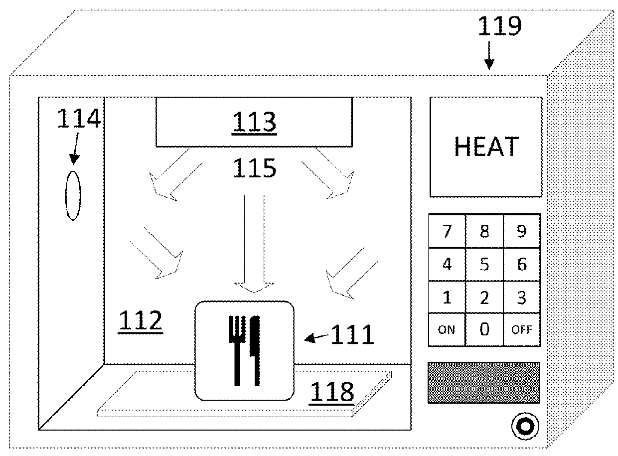
[0037]Control systems that use evaluative control to heat an item in a chamber of an electronic oven are disclosed. In some approaches the control systems use evaluative feedback. The output of the control system can include a power level and a relative position of a variable distribution of electromagnetic energy applied to a chamber of the oven with respect to an item in the chamber. The feedback to the control system can comprise visual light data, a surface temperature distribution of the item, or RF parameters associated with the absorption of electromagnetic energy by the chamber or item. In some approaches, the evaluative feedback is used to train the control system using a reinforcement learning training system. In some approaches, the control system generates a plan using a deterministic planner to heat the item. In some approaches, the evaluative feedback is used to learn the response of the item to a given action. The pairs of responses and actions can then be used to der...


PUM


Abstract

A disclosed computer-implemented method for heating an item in a chamber of an electronic oven towards a target state includes heating the item with a set of applications of energy to the chamber while the electronic oven is in a respective set of configurations. The set of applications of energy and respective set of configurations define a respective set of variable distributions of energy in the chamber. The method also includes sensing sensor data that defines a respective set of responses by the item to the set of applications of energy. The method also includes generating a plan to heat the item in the chamber. The plan is generated by a control system of the electronic oven and uses the sensor data.

Description

CROSS REFERENCE TO RELATED APPLICATIONS[0001]This application is a continuation of U.S. application Ser. No. 15 / 467,975, filed Mar. 23, 2017, which claims the benefit of U.S. Provisional Application No. 62 / 315,175, filed Mar. 30, 2016, U.S. Provisional Application No. 62 / 445,628 filed Jan. 12, 2017, U.S. Provisional Application No. 62 / 349,367, filed Jun. 13, 2016, and U.S. Provisional Application No. 62 / 434,179, filed Dec. 14, 2016, all of which are incorporated by reference herein in their entirety for all purposes.BACKGROUND OF THE INVENTION[0002]Electronic ovens heat items within a chamber by bombarding them with electromagnetic radiation. In the case of microwave ovens, the radiation most often takes the form of microwaves at a frequency of either 2.45 GHz or 915 MHz. The wavelength of these forms of radiation are 12 cm and 32.8 cm respectively. The waves within the microwave oven reflect within the chamber and cause standing waves. Standing waves are caused by two waves that ar...

Claims


Application Information

Patent Timeline
Patent Type & Authority Applications(United States)
IPC IPC(8): H05B1/02G05B19/042H05B6/64G06N99/00
CPCG05B2219/2643G05B19/042H05B1/0263H05B6/6455G06N99/005F24C7/085G05B19/0426F24C7/08G05D23/1917G05D23/27H05B6/687G06N3/006G06N3/084Y02B40/00G06N20/00G05D23/193
Inventor PEREIRA, ARVIND ANTONIO DE MENEZESSPEISER, LEONARD ROBERTLEINDECKER, NICK C.
Owner THE MARKOV CORP
Why Eureka
Try Eureka