End plate for a rear spoiler of a vehicle

a technology for rear spoilers and end plates, which is applied in the direction of aerodynamic improvement, transportation and packaging, light and heating equipment, etc., can solve the problems of passive end plates of rear spoilers, and are not capable of sensing active signaling functions of vehicles, so as to achieve cost-effective and simple manner

Active Publication Date: 2018-04-19
DR ING H C F PORSCHE AG
View PDF4 Cites 6 Cited by
  • Summary
  • Abstract
  • Description
  • Claims
  • Application Information

AI Technical Summary

Benefits of technology

[0005]Described herein is an end plate of a rear spoiler, which end plate can sense a signaling function for the vehicle in a cost-effective and simple manner.

Problems solved by technology

It is disadvantageous in the known solutions that the end plates of the rear spoilers are purely passive elements.
Although said end plates can provide additional influence on the flow conditions in the region of the rear spoiler, they, are not capable of sensing active signaling functions of the vehicle.

Method used


Image

  • End plate for a rear spoiler of a vehicle
  • End plate for a rear spoiler of a vehicle
  • End plate for a rear spoiler of a vehicle

Examples


Embodiment Construction

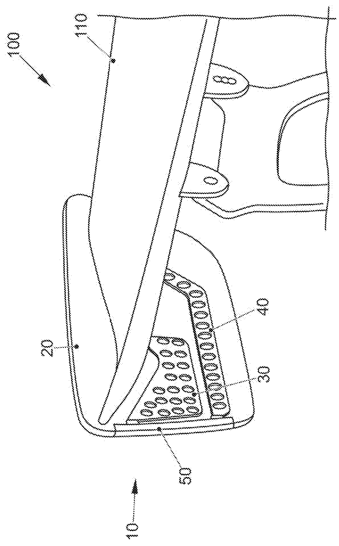
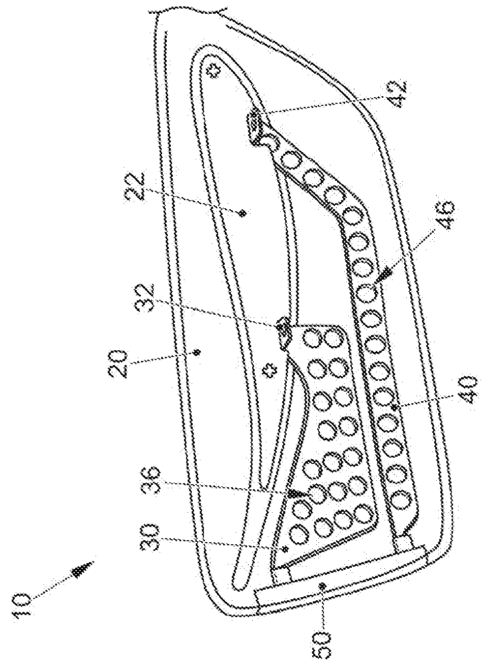
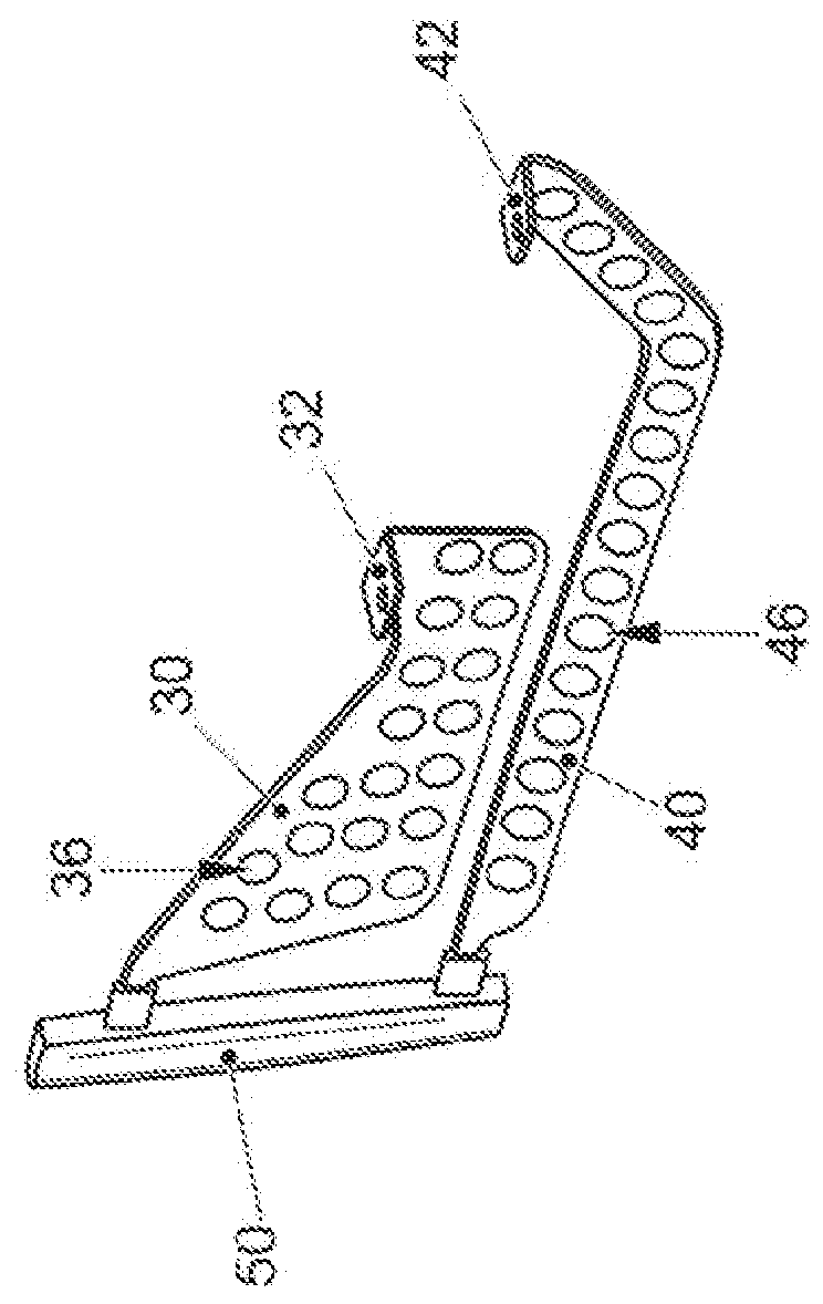
[0037]FIGS. 1 to 5 show an end plate 10 according to aspects of the invention which is assembled in FIGS. 1, 5 and 7 to form a rear spoiler 100 according to aspects of the invention. It can readily be seen in FIG. 1 how the end plate 10, which can preferably be arranged on both sides of an air directing element 110 of the rear spoiler 100, can be schematically formed. In particular, it can readily be seen in FIGS. 1 and 6 that an electric light element 50 is arranged on the rear edge of the basic body 20 of the respective end plate 10. This is, for example, a rear light or a brake light of the vehicle not illustrated specifically). As soon as a braking operation of the vehicle is initiated, the corresponding light element 50 has to be supplied with the information and the electric current which is intended to provide light functionality.

[0038]In order to be able to provide the above electric light functionality by means of the electric light element 50, two separate electric conduct...


PUM


Abstract

An end plate for a rear spoiler of a vehicle, having a basic body with a fastening portion for fastening to an air directing wing of the rear spoiler. A first electric conducting body and, insulated electrically therefrom, a second electric conducting body are arranged at least in sections within the basic body. An electric light element which is electrically conductively connected to the two conducting bodies is furthermore arranged on the basic body.

Description

CROSS-REFERENCE TO RELATED APPLICATIONS[0001]This application claims priority to German Patent Application No. DE 0 2016 119 699.1, filed Oct. 17, 2016, the content of such application being incorporated by reference herein in its entirety.FIELD OF THE INVENTION[0002]The present invention relates to an end plate for a rear' spoiler of a vehicle, and to a rear spoiler for a vehicle.BACKGROUND OF THE INVENTION[0003]It is known that vehicles are equipped with rear spoilers in order to improve the driving dynamics in respect of the flow of head wind around the vehicle. In order to ensure this, the rear spoiler is customarily equipped with at least one air directing wing which is responsible for influencing the air flow. The air directing wing is frequently provided on the two lateral end portions with what are referred to as end plates which preferably have a vertical or substantially vertical orientation.[0004]It is disadvantageous in the known solutions that the end plates of the rear...

Claims


Application Information

Patent Timeline
Patent Type & Authority Applications(United States)
IPC IPC(8): B60Q1/26B62D35/00B60Q1/22B60Q1/34B60Q1/44F21V23/06
CPCB60Q1/2661B62D35/007B60Q1/22B60Q1/34B60Q1/44F21V23/06B60Q1/0088Y02T10/82
Inventor ERB, THIEMOBRUNNER, MARKUSSAMEL, ERIK
Owner DR ING H C F PORSCHE AG
Why Eureka
Try Eureka