Display device and method of assembling it

Active Publication Date: 2018-04-19
ALPINE ELECTRONICS INC
View PDF14 Cites 3 Cited by
  • Summary
  • Abstract
  • Description
  • Claims
  • Application Information

AI Technical Summary

Benefits of technology

[0009]Due to the means described above, it is possible to provide a display device in which a force given to a display panel by a

Problems solved by technology

If, for example, a spacing between the two elastic boss portions is smaller than a spacing between the two openings due to, for example, manufacturing error, a bending load is generated that tends to cause the rear surface of the chassis member to warp.
This type of bending load generated due to a relationship in which constituent elements ar

Method used


Image

  • Display device and method of assembling it
  • Display device and method of assembling it
  • Display device and method of assembling it

Examples


Example

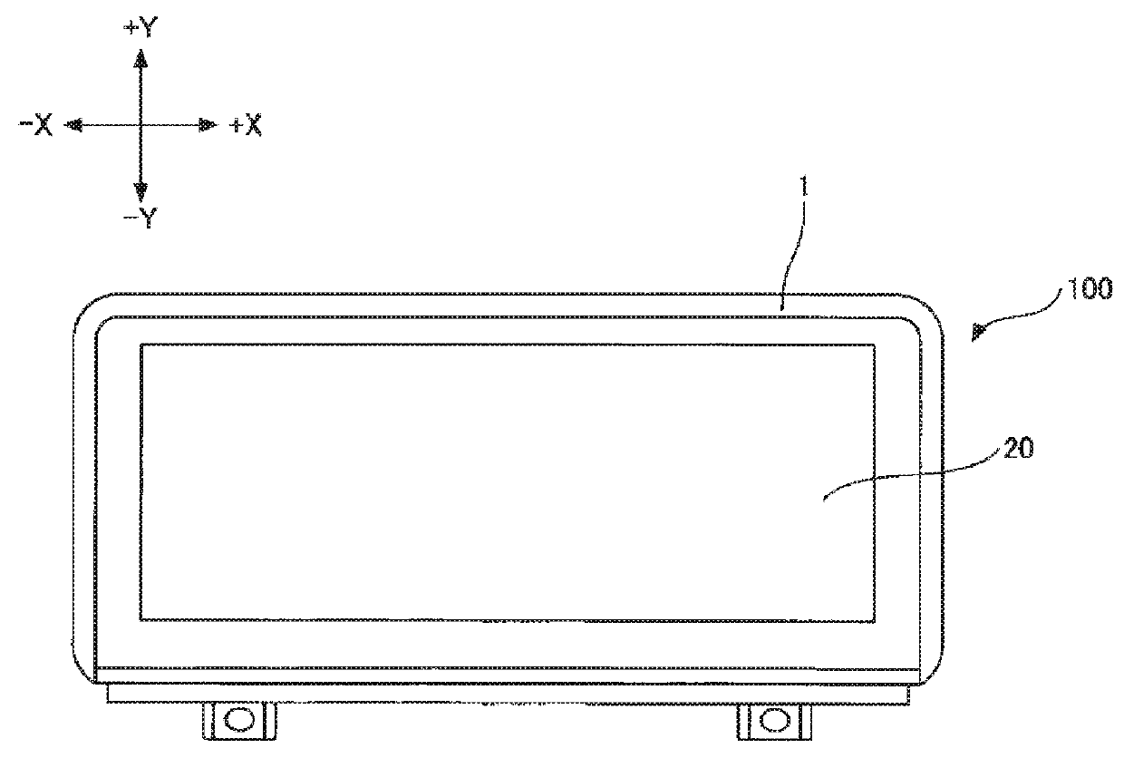
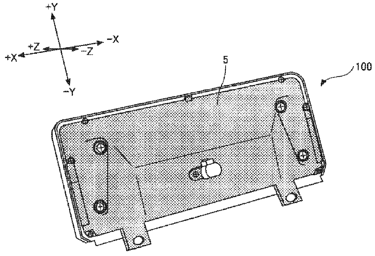
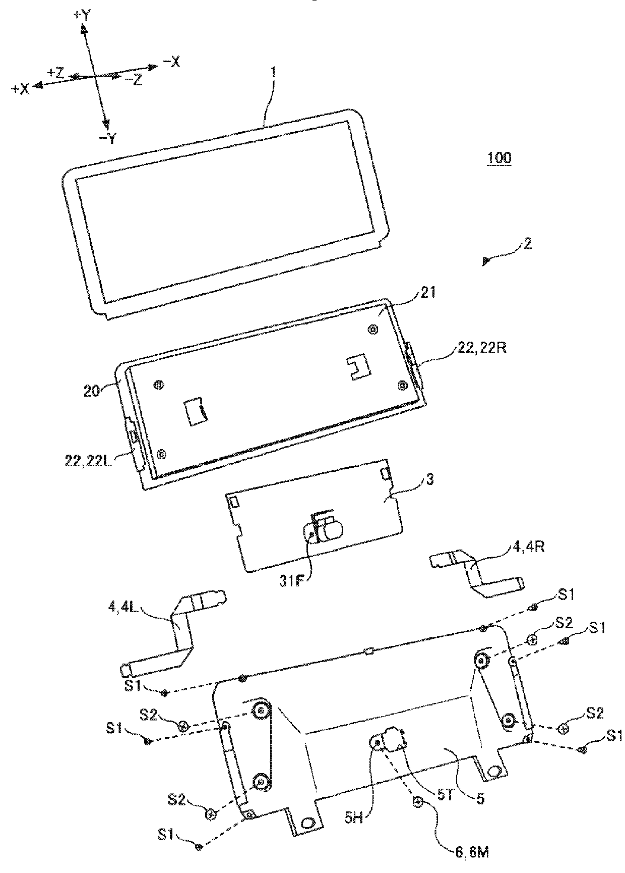
[0021]FIGS. 1A and 1B are schematic drawings illustrating a display device 100 in an embodiment of the present disclosure. Specifically, FIG. 1A is a front view of the display device 100, and FIG. 1B is a perspective view of the rear surface of the display device 100. FIG. 2 is an exploded perspective view of the rear surface of the display device 100. For convenience of explanation in this description, the front side of the display device 100 will be taken as the +Z side and the rear side will be taken as the −Z side. The upper side, lower side, right side, and left side when the front of the display device 100 is viewed from the +Z side will be respectively taken as the +Y side, −Y side, +X side, and −X side.

[0022]The display device 100 is, for example, a liquid crystal display device. However, the display device 100 may be another type of display device such as a plasma display device or an organic electroluminescent (EL) display device. As illustrated in FIG. 2, the display devi...


PUM


Abstract

A display device includes a display module, a rear cover that covers the rear surface of the display module, a main circuit board placed in an internal space formed between the rear cover and the rear surface of the display module, flexible wiring members that mutually connects the display module and the main circuit board, and a male screw having a head exposed to the outside of the rear cover, the male screw passing through the rear cover and engaging a female screw formed in the main circuit board. The main circuit board is fixed to the rear cover with the male screw in a state in which the main circuit board is not fixed to the display module.

Description

RELATED APPLICATION[0001]The application claims priority to Japanese Patent Application Number 2016-204243, filed Oct. 18, 2016, the entirety of which is hereby incorporated by reference.BACKGROUND1. Field[0002]The present disclosure relates to a display device and a method of assembling it.2. Description of the Related Art[0003]A conventional plasma display device known in the related art includes a chassis member bonded to the rear surface of a plasma display panel and also includes a holding plate on which an address driver circuit and other driving circuit portions are mounted (see Japanese Unexamined Patent Application Publication No. 2008-256771). To fix the holding plate to the rear surface of the chassis member, two elastic boss portions provided on the chassis member are inserted into two openings formed in the holding plate while the elastic boss portions are deformed so as to be contracted. The holding plate is also fixed by being held by two clips made of an elastic meta...

Claims


Application Information

Patent Timeline
IPC IPC(8): H05K5/00H05K5/02
CPCH05K5/0017H01J17/49H05K5/0247H04N5/655G06F1/1601G02F1/133314G02F1/133308H05K5/02
Inventor ODA, KAZUKIKIDA, SHINOBU
Owner ALPINE ELECTRONICS INC
Why Eureka
Try Eureka