

Monitoring system, monitoring device, and monitoring method
a monitoring system and monitoring device technology, applied in the direction of optical radiation measurement, diagnostics using spectroscopy, instruments, etc., to achieve the effect of grasping the situation more efficiently
- Summary
- Abstract
- Description
- Claims
- Application Information
AI Technical Summary
Benefits of technology
Problems solved by technology
Method used
Image

Examples
first embodiment
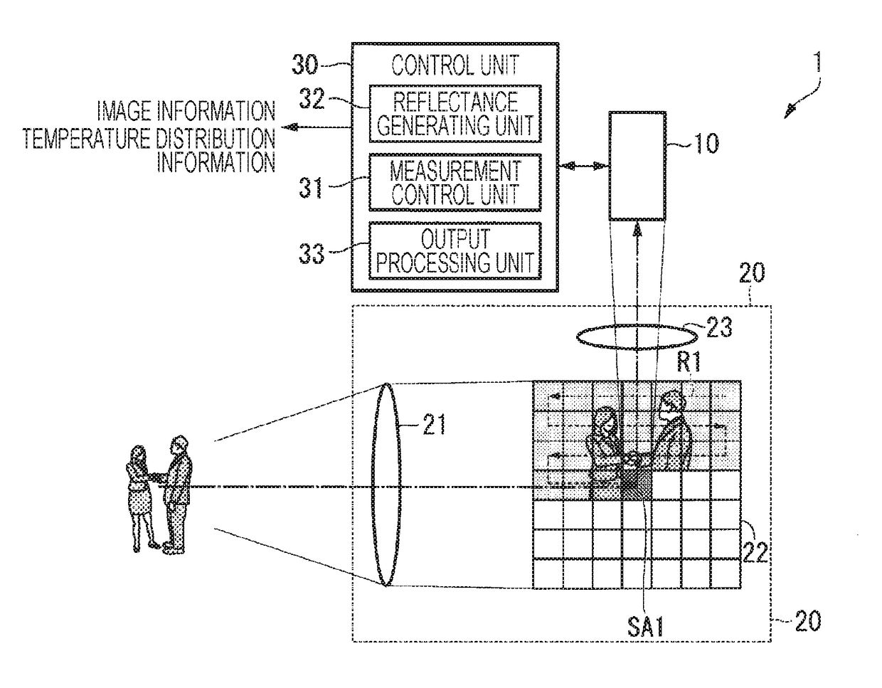
[0048]FIG. 1 is a diagram showing a configuration example of a measuring device 1 according to a first embodiment.
[0049]As shown in FIG. 1, the measuring device 1 includes a sensor unit 10, an optical system 20, and a control unit 30.
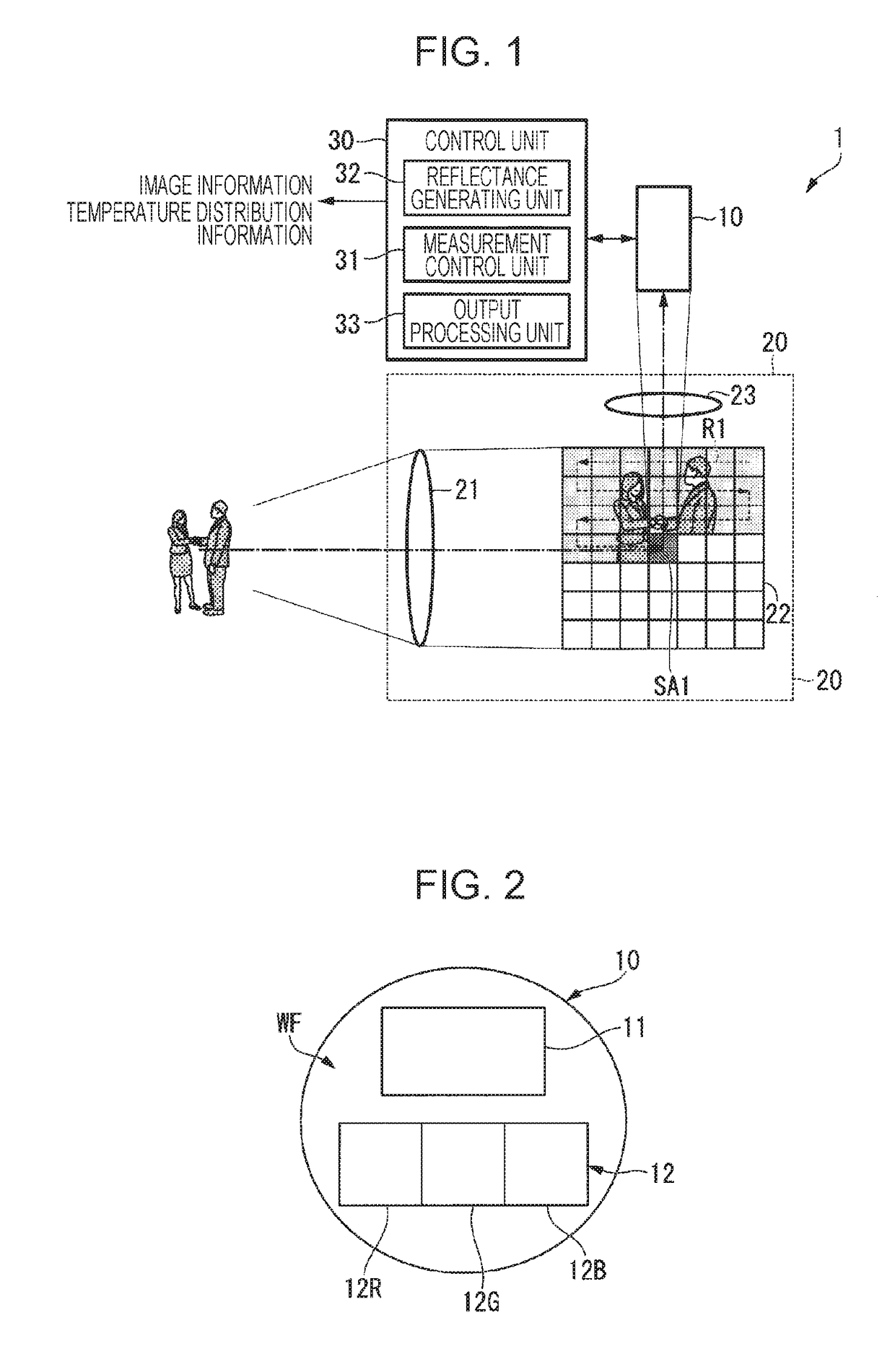
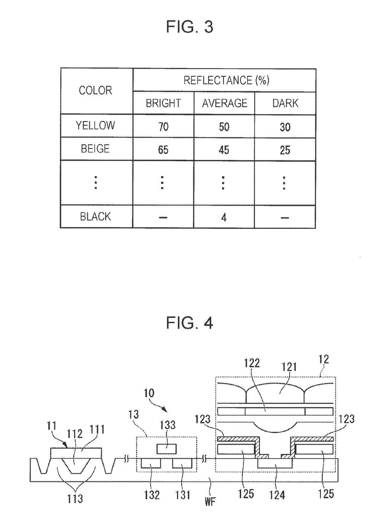
[0050]The sensor unit 10 (an example of the integrated circuit) is, for example, a semiconductor device that detects the temperature of an object (object to be measured) in a non-contact manner. Based on the infrared light reflected from the object, the sensor unit 10 detects the temperature of the object and detects an image of the object based on the visible light reflected from the object. The sensor unit 10 includes, for example, a thermopile unit 11 and a photodiode unit 12 as shown in FIG. 2.
[0051]FIG. 2 is a diagram showing a configuration example of an incident surface of light of the sensor unit 10 according to the present embodiment. Here, this diagram shows the sensor unit 10 as seen from an incident surface (sensor surface) side.
[0052]As sho...
second embodiment
[0104]Next, the operation of the measuring device according to the second embodiment will be described with reference to the drawing.
[0105]FIG. 6 is a diagram showing a configuration example of a measuring device 1a according to a second embodiment. In addition, FIG. 7 is a diagram showing a configuration example of an incident surface of light of a sensor unit 10a according to the second embodiment.
[0106]In FIGS. 6 and 7, the same components as those shown in FIGS. 1 and 2 are denoted by the same reference numerals, and the description thereof will be omitted.
[0107]As shown in FIG. 6, the measuring device 1a according to the present embodiment includes a sensor unit 10a, the optical system 20, and the control unit 30. In addition, the sensor unit 10a includes an image correction unit 14.
[0108]In addition, as shown in FIG. 7, the sensor unit 10a includes the thermopile unit 11 and a plurality of photodiode units 12 (12-1, 12-2, 12-3, 12-4) on the same semiconductor substrate WF. Her...
third embodiment
[0121]Next, the monitoring system according to the third embodiment will be described with reference to the drawing.
[0122]In the present embodiment, using the above-described measuring device 1 (1a), a monitoring system is described that monitors persons with a fever, for example at an airport, station, public facility, and the like and predicts an occurrence transition of the persons with a fever.
[0123]FIG. 8 is a functional block diagram showing an example of a monitoring system 100 according to the present embodiment.
[0124]As shown in FIG. 8, the monitoring system 100 includes the above-described plurality of measuring devices 1 (1a), a plurality of environment detection unit 40, and a monitoring device 50.
[0125]Either the measuring device 1 of the above-described first embodiment or the measuring device 1a of the second embodiment is applicable to the monitoring system 100, but in the present embodiment, for explanation purposes, the monitoring system 100 to which the measuring ...
PUM
 Abstract
Description
Claims
Application Information