
Inkjet printhead assembly with compact repositionable shutter

a repositionable shutter and printhead technology, applied in printing, printing mechanisms, printing, etc., can solve the problems of skewing images, increased cost of manufacturing the alignment baseplate to accommodate the increase in print width, and overflow of the available printhead width, etc., to achieve compact and inexpensive manufacturing, easy to remove and replace, and easy to manufacture

Active Publication Date: 2018-05-10
EASTMAN KODAK CO
View PDF0 Cites 0 Cited by
  • Summary
  • Abstract
  • Description
  • Claims
  • Application Information

AI Technical Summary

Benefits of technology

[0021]This invention has the advantage that the repositionable shutter mechanism is compact and inexpensive to manufacture.
[0022]It has the additional advantage that the repositionable shutter mechanism can be easily removed and replaced.

Problems solved by technology

However, for many applications the desired print width exceeds the width of the available printheads.
It has also been found that as the desired print width increases, the cost for manufacturing the alignment baseplate to accommodate the increased print width increases significantly.
It has been found that a skew of the drop selection hardware relative to the nozzle array can contribute to a skew of the images printed by the printhead relative to the print swaths of other printheads in an array of printheads.
Prior art shutter arrangements have been found to limit the spacing between printhead rows, and to limit the effectiveness for performing various maintenance operations.

Method used


Image

  • Inkjet printhead assembly with compact repositionable shutter
  • Inkjet printhead assembly with compact repositionable shutter
  • Inkjet printhead assembly with compact repositionable shutter

Examples


Embodiment Construction

[0047]The present description will be directed in particular to elements forming part of, or cooperating more directly with, apparatus in accordance with the present invention. It is to be understood that elements not specifically shown or described may take various forms well known to those skilled in the art. References to “a particular embodiment” and the like refer to features that are present in at least one embodiment of the invention. Separate references to “an embodiment” or “particular embodiments” or the like do not necessarily refer to the same embodiment or embodiments; however, such embodiments are not mutually exclusive, unless so indicated or as are readily apparent to one of skill in the art. The use of singular or plural in referring to the “method” or “methods” and the like is not limiting. It should be noted that, unless otherwise explicitly noted or required by context, the word “or” is used in this disclosure in a non-exclusive sense.

[0048]The example embodiment...


PUM


Abstract

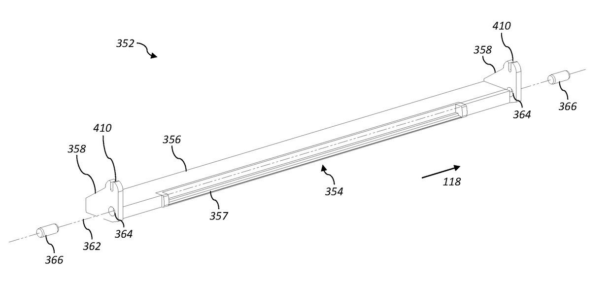
An inkjet printhead assembly includes a repositionable shutter mechanism adapted to block a slot through which drops of ink ejected from the array of nozzles pass before they impinge on the print medium. The shutter mechanism includes an actuator rod having a first actuation feature, and a repositionable shutter blade extending in a cross-track direction having first and second tabs affixed to its ends. The first tab includes a second actuation feature that engages with the first actuation feature of the actuator rod. An actuator is configured to translate the actuator rod, thereby pivoting the repositionable shutter blade about the pivot axis between a first pivot position where the shutter blade blocks the slot and a second pivot position where the shutter blade is moved away from the slot so that drops of ink can pass through the slot.

Description

CROSS REFERENCE TO RELATED APPLICATIONS[0001]Reference is made to commonly assigned, co-pending U.S. patent application Ser. No. 15 / 163,235, entitled: “Modular printhead assembly with common center rail”, by M. Piatt et al.; to commonly assigned, co-pending U.S. patent application Ser. No. 15 / 163,243, entitled: “Printhead assembly with removable jetting module”, by J. Brazas et al.; to commonly assigned, co-pending U.S. patent application Ser. No. 15 / 163,249, entitled: “Inkjet printhead assembly with repositionable shutter”, by D. Tunmore et al.; to commonly assigned, co-pending U.S. patent application Ser. No. 15 / 299,749, entitled: “Modular printhead assembly with tilted printheads,” by D. Tunmore; and to commonly assigned, co-pending U.S. patent application Ser. No. ______ (Docket K002124), entitled: “Inkjet printhead assembly with repositionable shutter mechanism,” by D. Tunmore, each which is incorporated herein by reference.FIELD OF THE INVENTION[0002]This invention pertains to...

Claims


Application Information

Patent Timeline
Patent Type & Authority Applications(United States)
IPC IPC(8): B41J2/17
CPCB41J2/1721B41J2/085B41J2/09B41J2/175B41J2/1752B41J2/17553B41J2/18B41J2/185B41J29/02B41J29/38B41J2002/1853B41J2/2146B41J25/001B41J25/003B41J25/304B41J25/316
Inventor ROBERTS, JEFFREY L.PIATT, MICHAEL J.KATERBERG, JAMES A.
Owner EASTMAN KODAK CO
Learn More