
Voltage regulation device

a voltage regulation device and voltage technology, applied in the direction of electric variable regulation, process and machine control, instruments, etc., can solve the problems of resistive heating loads such as electric showers, immersion heaters, cookers, etc., and achieve the effect of convenient installation, compactness and inexpensive manufactur

Inactive Publication Date: 2010-07-13
VPHASE SMART ENERGY
View PDF10 Cites 2 Cited by
  • Summary
  • Abstract
  • Description
  • Claims
  • Application Information

AI Technical Summary

Benefits of technology

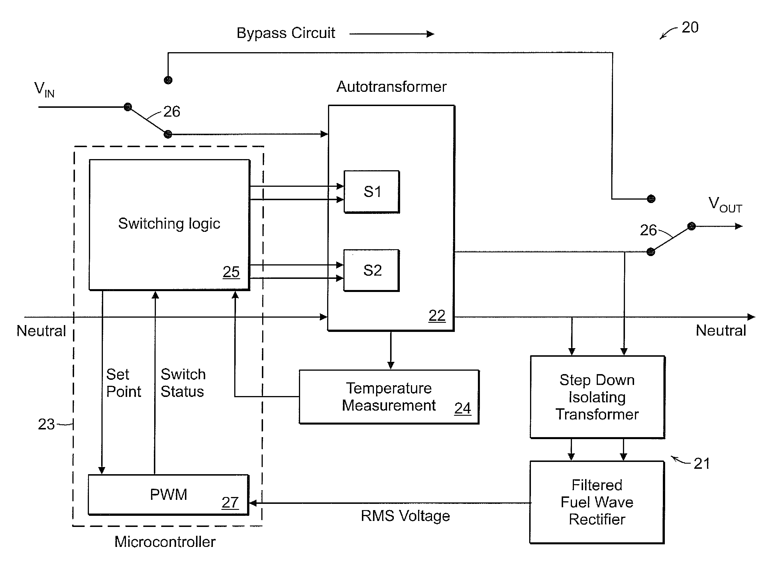
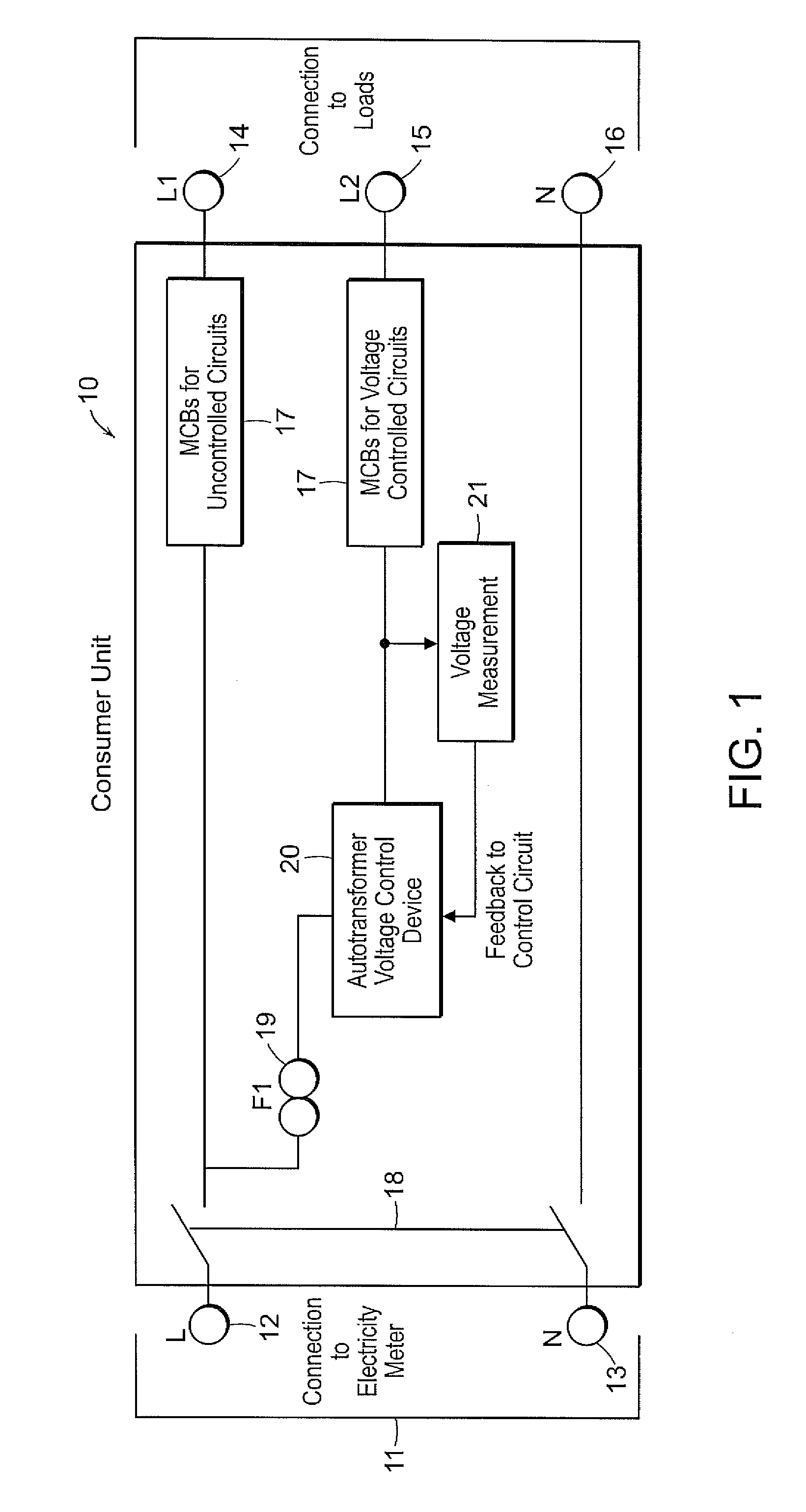
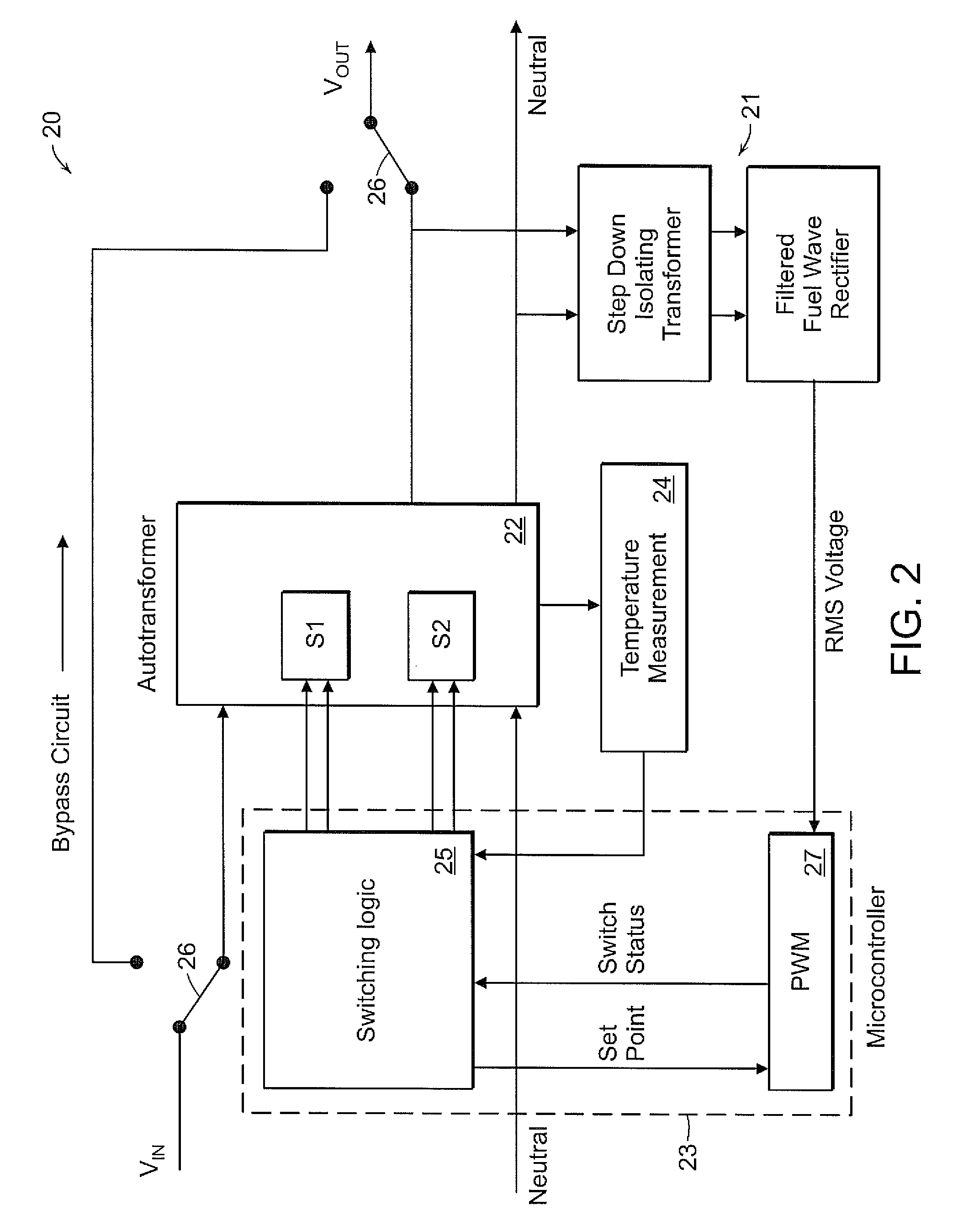
"The present invention provides a voltage regulation device that is small, lightweight, and inexpensive to manufacture. The device includes an autotransformer and cyclic switching means to control its output voltage. The device can be connected to a property's electrical supply and is responsive to changes in the autotransformer's operating temperature to control its output voltage. The device can be used to regulate the voltage supplied to appliances that benefit from voltage regulation, while avoiding the need to switch in lossy snubber circuits. The device can be contained within a domestic electrical consumer unit and connected between the main electrical supply and the circuits that will benefit from voltage regulation."

Problems solved by technology

This requires an autotransformer having a rating of something like 24 kVA which is physically very large, heavy and expensive.
Testing has confirmed that some loads benefit greatly from voltage regulation, for instance lighting circuits, refrigerator / freezer and appliances containing motors or transformers, whereas resistive heating loads such as electric showers, immersion heaters and cookers do not benefit from voltage control.

Method used


Image

  • Voltage regulation device
  • Voltage regulation device
  • Voltage regulation device

Examples


Embodiment Construction

[0019]For the purpose of this description it will be assumed that the voltage regulation device is adapted for connection to a varying electrical supply operating within a range of 230V plus or minus 10% which is the statutory range required under European electrical power legislation, and it will further be assumed that a constant output voltage of 230V is to be maintained by the device.

[0020]Referring now to FIG. 1 a domestic consumer unit is represented at 10 and is supplied with electricity from a meter 11 having output live and neutral terminals 12 and 13 respectively. Within the consumer unit 10 the live supply is divided to supply two live output terminals 14 and 15 and a neutral output terminal 16. MCBs or other safety devices 17 are included in the supplies to each of the terminals 14 and 15. Terminals 14 and 16 are connected by a main isolating switch 18 directly to the terminals 12 and 13, via the associated MCBs 17, in the case of terminal 14.

[0021]In accordance with the...


PUM


Abstract

A voltage regulation device adapted for connection to a varying electrical supply and to regulate the voltage supplied to certain selected circuits whose loads benefit from voltage regulation. The device comprises a PWM or phase angle switched autotransformer which is sufficiently compact and lightweight to be incorporated into a standard electrical consumer unit which has separated circuits, ie, those whose loads benefit from voltage regulation and those whose loads do not, such that the former may be controlled by the device to operate at a constant and reduced voltage thus ensuring a reduction in energy consumption and the life enhancement of the appliances connected to the device. The operating temperature of the autotransformer is controlled by temporarily increasing the output voltage of the autotransformer in the event of overheating.

Description

PRIORITY INFORMATION[0001]This application is a continuation of International Application No. PCT / GB2005 / 003121 filed on Aug. 10, 2005 which is incorporated by reference in its entirety herein.BACKGROUND OF THE INVENTION[0002]1. Field of the Invention[0003]This invention relates to the control of the voltage of the electrical supply to a property for the purpose of energy saving and to improve the performance of, and prolong the life of, electrical appliances connected to the supply, and further concerns a voltage regulation device for such purpose.[0004]2. Brief Description of the Art[0005]In many parts of the world electrical distribution companies deliver power to end users at the upper end of a permitted range of voltage. For example, a typical average supply voltage in the UK and certain other parts of the world may be around 240 volts where the permitted statutory European voltage range is 216-252V. To reduce the supplied voltage to, say, 230V would have no negative impact upo...

Claims


Application Information

Patent Timeline
Patent Type & Authority Patents(United States)
IPC IPC(8): G05F1/12G05F1/14
CPCH02M1/425H02M5/12H02M5/22Y02B70/126Y02B70/10
Inventor REDFORD, SIMON JAMESJUBY, LEEDERBY, JAMES WILLIAMMANGAN, STEPHEN JAMES
Owner VPHASE SMART ENERGY
Learn More