

Substrate processing apparatus, injector, and substrate processing method
a substrate processing and injector technology, applied in the direction of coatings, chemical vapor deposition coatings, metallic material coating processes, etc., can solve the problems of troublesome maintenance work and inability to perform the original gas supply
- Summary
- Abstract
- Description
- Claims
- Application Information
AI Technical Summary
Benefits of technology
Problems solved by technology
Method used
Image

Examples
first embodiment
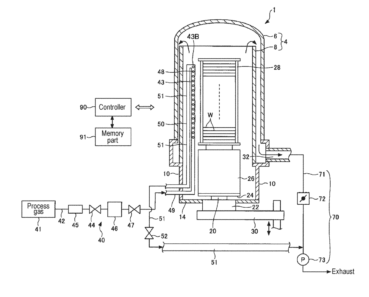
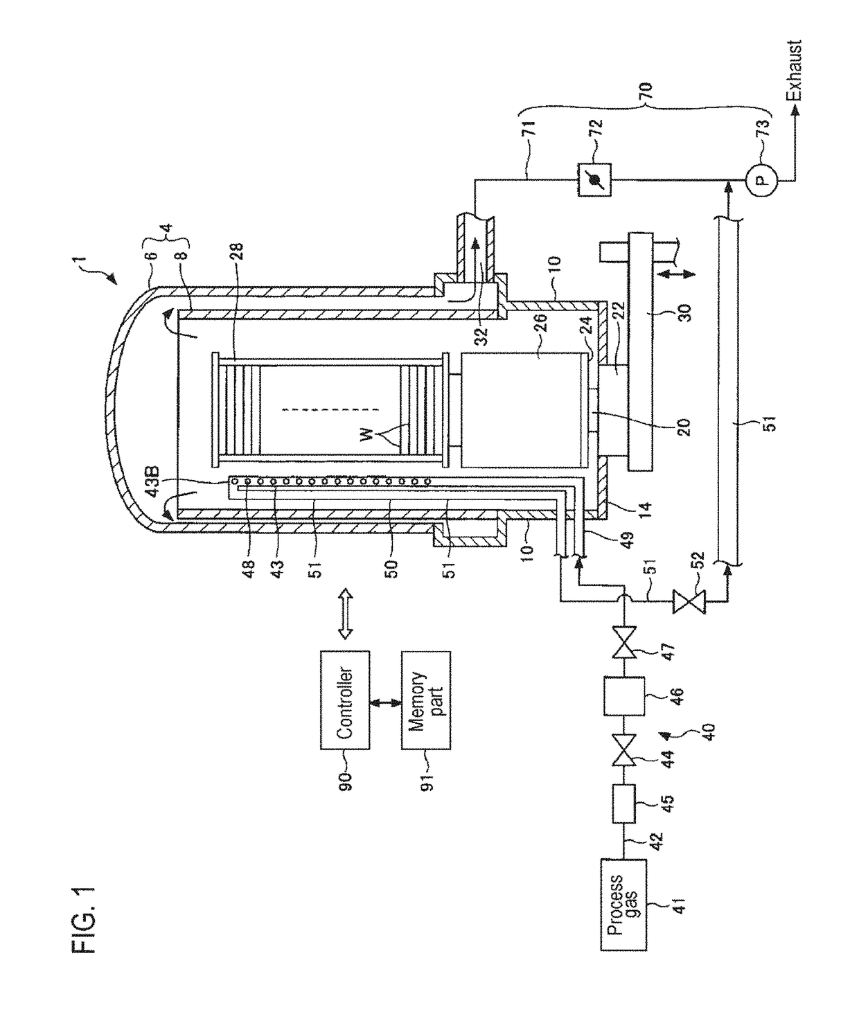
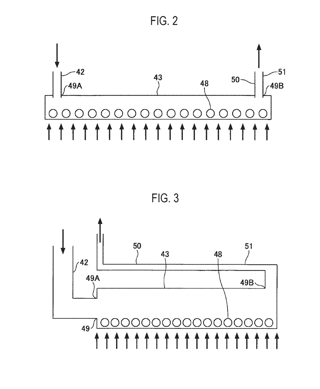
[0045]First, in the first embodiment, as illustrated in FIGS. 1 and 2, at least one end portion of the gas nozzle 43 communicates with the gas pipe 42 of the gas supply line 40, and the other end portion thereof communicates with the scavenging line 50. Furthermore, the gas discharge holes 48 of the gas nozzle 43 are formed as a plurality of gas holes which communicate with the interior of the reaction vessel 4 and constitute a supply port for supplying the process gas into the reaction vessel 4.
[0046]Openings 49 (openings 49A and 49B) are formed in both end portions of the gas nozzle 43. The opening 49A formed in one end portion constitutes an introduction port for introducing the process gas from the gas pipe 42 of the gas supply line 40 into the gas nozzle 43. Furthermore, the opening 49B formed in the other end portion constitutes a discharge port for discharging the scavenging gas to the gas pipe 51 of the scavenging line 50. That is, the gas nozzle 43 communicates with the gas...
second embodiment
[0050]Furthermore, in the second embodiment, as illustrated in FIG. 3, the gas pipe 42 of the gas supply line 40 is formed in an L shape near the opening 49A of the gas nozzle 43. That is, the gas pipe 42, while its end portion is bent, is connected to the opening 49A of the gas nozzle. With this configuration, the gas pipe 42 can be installed on the sidewall (manifold 10) of the reaction vessel 4 to facilitate the operation of arranging the gas supply line 40.
[0051]In the third embodiment, as illustrated in FIG. 4, a portion of the scavenging line 50 (gas pipe 51) is arranged inside the gas nozzle 43. That is, a portion of the gas pipe 51 of the scavenging line 50 and the gas nozzle 43 constitute a double tube. In the configuration of the third embodiment, a portion of the gas pipe 51 of the scavenging line 50 is also arranged inside the gas pipe 42 connected to the gas nozzle 43. With this configuration, since a portion of a space necessary for arranging the gas pipe 51 of the sca...
fifth embodiment
[0053]In the fifth embodiment, as illustrated in FIG. 6, one gas hole of the gas discharge hole 48 is formed. In this case, the gas nozzle 43 may be formed in at least one end portion of the gas nozzle 43 as a gas hole opened in the reaction vessel 4. In this manner, the scavenging line 50 can be installed irrespective of the number of gas holes.
[0054]In addition, in the configuration of the fifth embodiment, the gas discharge hole 48 is formed in the other end portion of the gas nozzle 43 (on the side of the opening 49B communicating with the scavenging line 50). In such a configuration, since the gas hole is arranged near the opening 49B (discharge port) communicating with the scavenging line 50, it is possible to efficiently scavenge the gas including the particle source near the gas hole.
[0055]Furthermore, in the sixth embodiment, as illustrated in FIG. 7, in a state in which the configuration of the fifth embodiment is employed, a portion of the double tube constituted by a por...
PUM
| Property | Measurement | Unit |
|---|---|---|
| Pressure | aaaaa | aaaaa |
Abstract
Description
Claims
Application Information