
Method of parallel shift operation of multiple reactors

a technology of multiple reactors and shift operations, applied in mechanical equipment, transportation and packaging, coatings, etc., can solve the problems of reducing productivity, increasing the number of system components, and increasing the process cycle tim

Active Publication Date: 2014-12-16
ASM IP HLDG BV
View PDF7 Cites 382 Cited by
  • Summary
  • Abstract
  • Description
  • Claims
  • Application Information

AI Technical Summary

Benefits of technology

The patent describes a method and apparatus for parallel shift operation of multiple reactors, which reduces the number of system components and significantly reduces the transition time. The method involves supplying n gases to the n reactors simultaneously at a constant flow rate, while maintaining the inflow and outflow rates of the reactors. The method can be used in semiconductor processing and is particularly useful for cyclic CVD or ALD. The apparatus includes multiple reactors, main gas lines, gas ports, and branch gas lines, which are connected to the gas ports. The invention allows for efficient and effective parallel shift operation of multiple reactors.

Problems solved by technology

Therefore, this flow control system is not adopted in the case where the RC pressure difference between RCs could cause a problem (e.g. improper precursor gas inflow goes to a wrong RC via a shared exhaust line due to the pressure difference between the RCs).
However, any cyclic deposition (e.g., cyclic CVD, thermal ALD, radical-enhanced ALD, etc.) using multiple reaction chambers has similar problems in increasing the number of system components.
Thus, changing gases increases process cycle time, lowering productivity.
The transition time and the dilution of reactant gas are unavoidable in conventional cyclic deposition.

Method used


Image

  • Method of parallel shift operation of multiple reactors
  • Method of parallel shift operation of multiple reactors
  • Method of parallel shift operation of multiple reactors

Examples


Embodiment Construction

[0081]In this disclosure, “gas” may include vaporized solid and / or liquid and may be constituted by a single gas or a mixture of gases. In this disclosure, “a” refers to a species or a genus including multiple species. Further, in this disclosure, any two numbers of a variable can constitute an workable range of the variable as the workable range can be determined based on routine work, and any ranges indicated may include or exclude the endpoints. Additionally, any values of variables indicated may refer to precise values or approximate values and include equivalents, and may refer to average, median, representative, majority, etc. in some embodiments.

[0082]In the present disclosure where conditions and / or structures are not specified, the skilled artisan in the art can readily provide such conditions and / or structures, in view of the present disclosure, as a matter of routine experimentation.

[0083]In all of the disclosed embodiments, any element used in an embodiment can be replac...


PUM

PropertyMeasurementUnit
transition timeaaaaaaaaaa
constant flow rateaaaaaaaaaa
total flow rateaaaaaaaaaa

Abstract

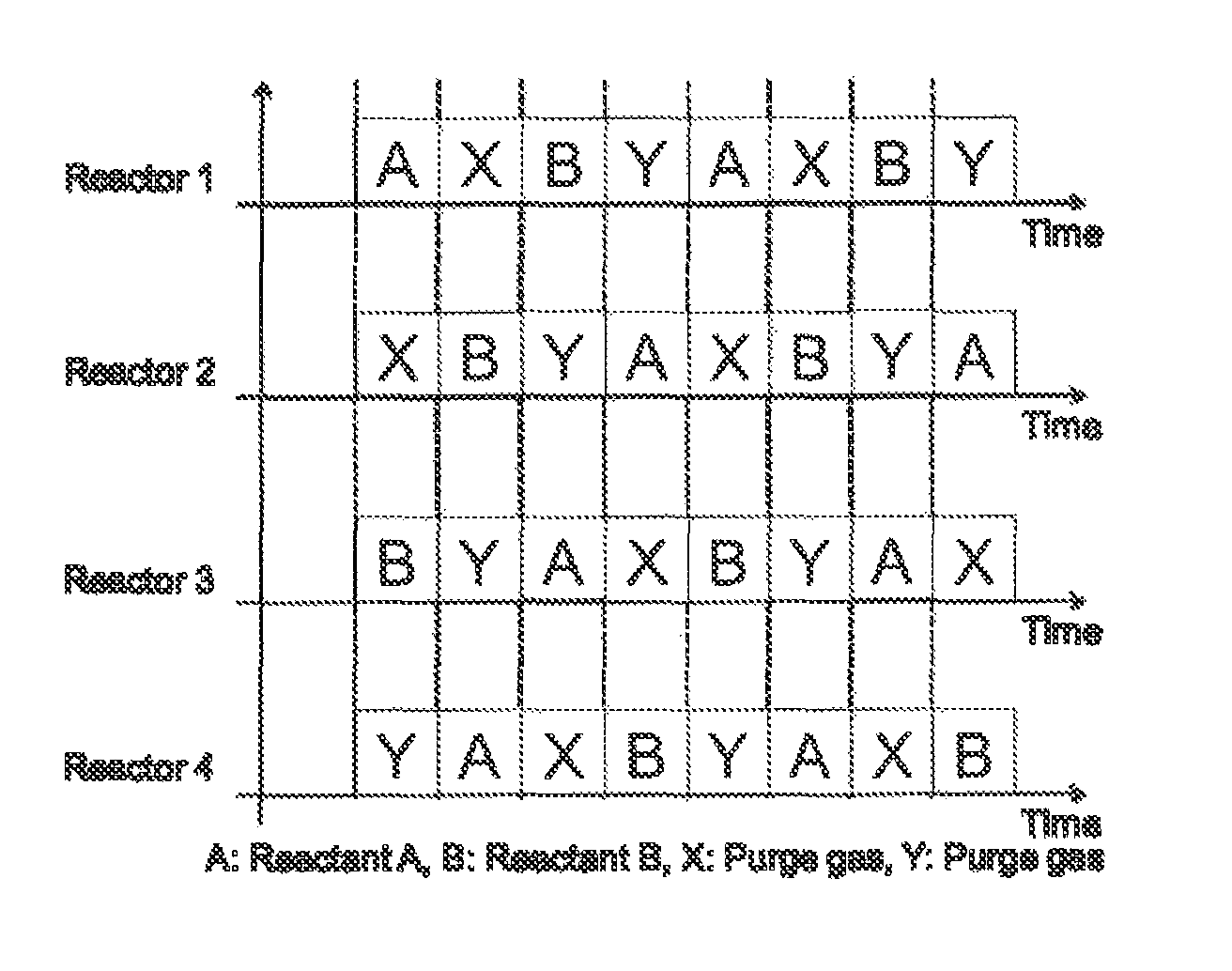
A method of parallel shift operation of multiple reactors includes: (i) continuously supplying n gases numbered 1 to n simultaneously to n gas ports via n main gas lines, respectively, at a constant flow rate, wherein one of branch gas lines of each main gas line is in an open state so that the inflow rates of the respective reactors are equal, and the outflow rates of the respective reactors are equal; and (ii) while maintaining the inflow rates and the outflow rates of the respective reactors, simultaneously closing the one of the branch gas lines of each main gas line in the open state and opening another one of the branch gas lines of each main gas line so that different numbered gases are continuously supplied to the respective reactors in parallel without changing the inflow rates and the outflow rates of the reactors.

Description

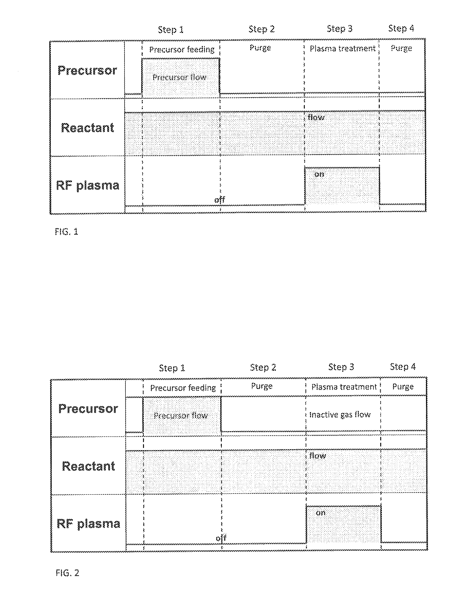
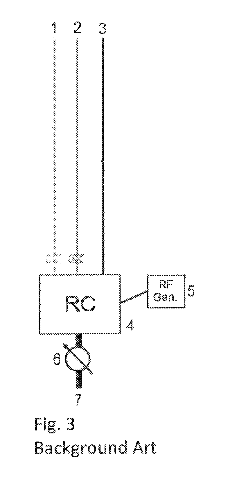
BACKGROUND[0001]1. Field of the Invention[0002]The present invention generally relates to a semiconductor-manufacturing method, particularly to a method of parallel shift operation of multiple reactors wherein gases are continuously supplied to the reactors.[0003]2. Description of the Related Art[0004]A plasma-enhanced atomic layer deposition (PEALD) process typically repeats the following four steps as illustrated in FIG. 1:[0005]In step 1 (Precursor feeding), a precursor gas is supplied into a reactor chamber (RC) and the precursor is adsorbed onto a wafer surface. In step 2 (Purge), non-adsorbed precursor is removed from the reactor chamber. In step 3 (Plasma treatment), the adsorbed surface is activated by RF plasma for reaction of the precursor with a reactant gas. In step 4 (Purge), non-reacted precursor and by-products are removed from the surface. In the above, during the steps, the reactant gas continuously flows. Equipment for the PEALD process requires the following compo...

Claims


Application Information

Patent Timeline
Patent Type & Authority Patents(United States)
IPC IPC(8): C23C16/52F17D3/00
CPCF17D3/00C23C16/45542C23C16/52Y10T137/0357H01L21/0228H01L21/0262
Inventor ADACHI, WATARUHA, JEONGSOK
Owner ASM IP HLDG BV
Learn More