Gas distribution system and method for distributing process gas in a processing system

a technology of process gas and processing system, which is applied in the direction of coating, chemical vapor deposition coating, metallic material coating process, etc., can solve the problems of not being able to easily and/or quickly replace, and the system cannot be easily changed to accommodate the process

Active Publication Date: 2012-08-28
TOKYO ELECTRON LTD
View PDF48 Cites 382 Cited by
  • Summary
  • Abstract
  • Description
  • Claims
  • Application Information

AI Technical Summary

Benefits of technology

[0011]A method for distributing the process gas into the process chamber of a deposition system is also provided. The method includes introducing the process gas into the inlet of the vapor distribution system described above, moving the piston to a desired location in the plenum, flowing the process gas from the inlet to the upper plenum portion located between the outer circumferential edge of the housing and the piston and further to the lower plenum portion located between the piston and the vapor distribution plate, and flowing the process gas through the plurality of orifices in the vapor distribution plate and into the process chamber of the deposition system. The desired location of the piston determines the relative flow of process gas through the central radial portion of the vapor distribution plate and the outer radial portion of the vapor distribution plate.

Problems solved by technology

In addition, the vapor distribution plate is fixed in the system and not easily and / or quickly replaceable, such that the system cannot be easily changed to accommodate process parameter changes or to accomplish uniform flow or center-enhanced flow in the event that edge-enhanced flow is not desired.

Method used


Image

  • Gas distribution system and method for distributing process gas in a processing system
  • Gas distribution system and method for distributing process gas in a processing system
  • Gas distribution system and method for distributing process gas in a processing system

Examples


Embodiment Construction

[0017]In the following description, in order to facilitate a thorough understanding of the invention and for purposes of explanation and not limitation, specific details are set forth, such as a particular geometry of the deposition system and descriptions of various components. However, it should be understood that the invention may be practiced in other embodiments that depart from these specific details.

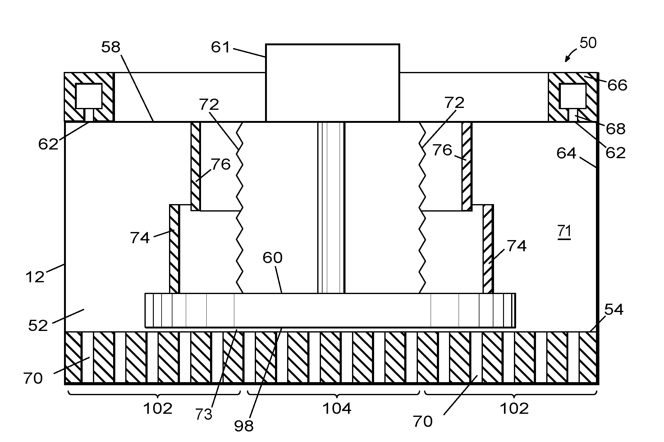
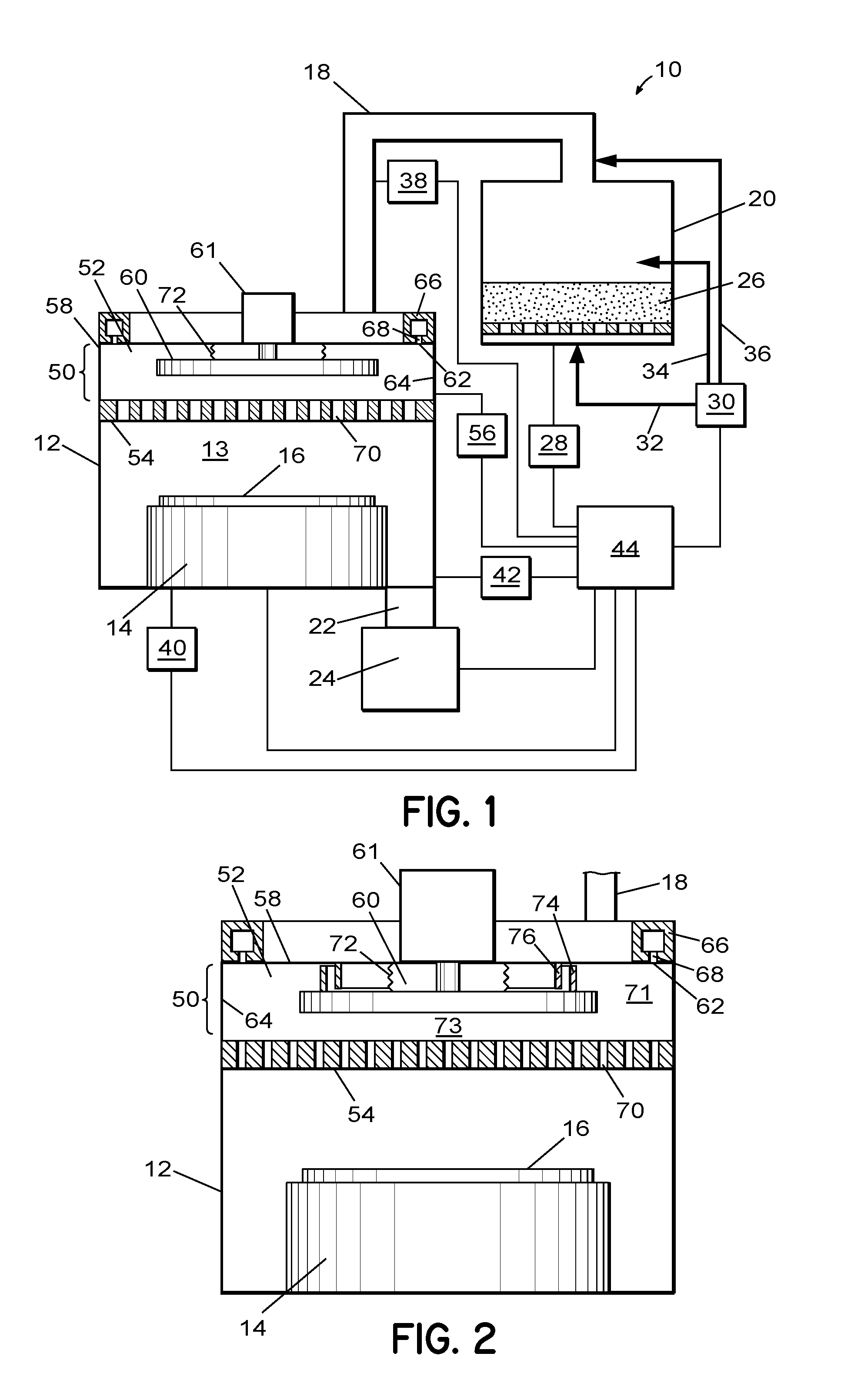
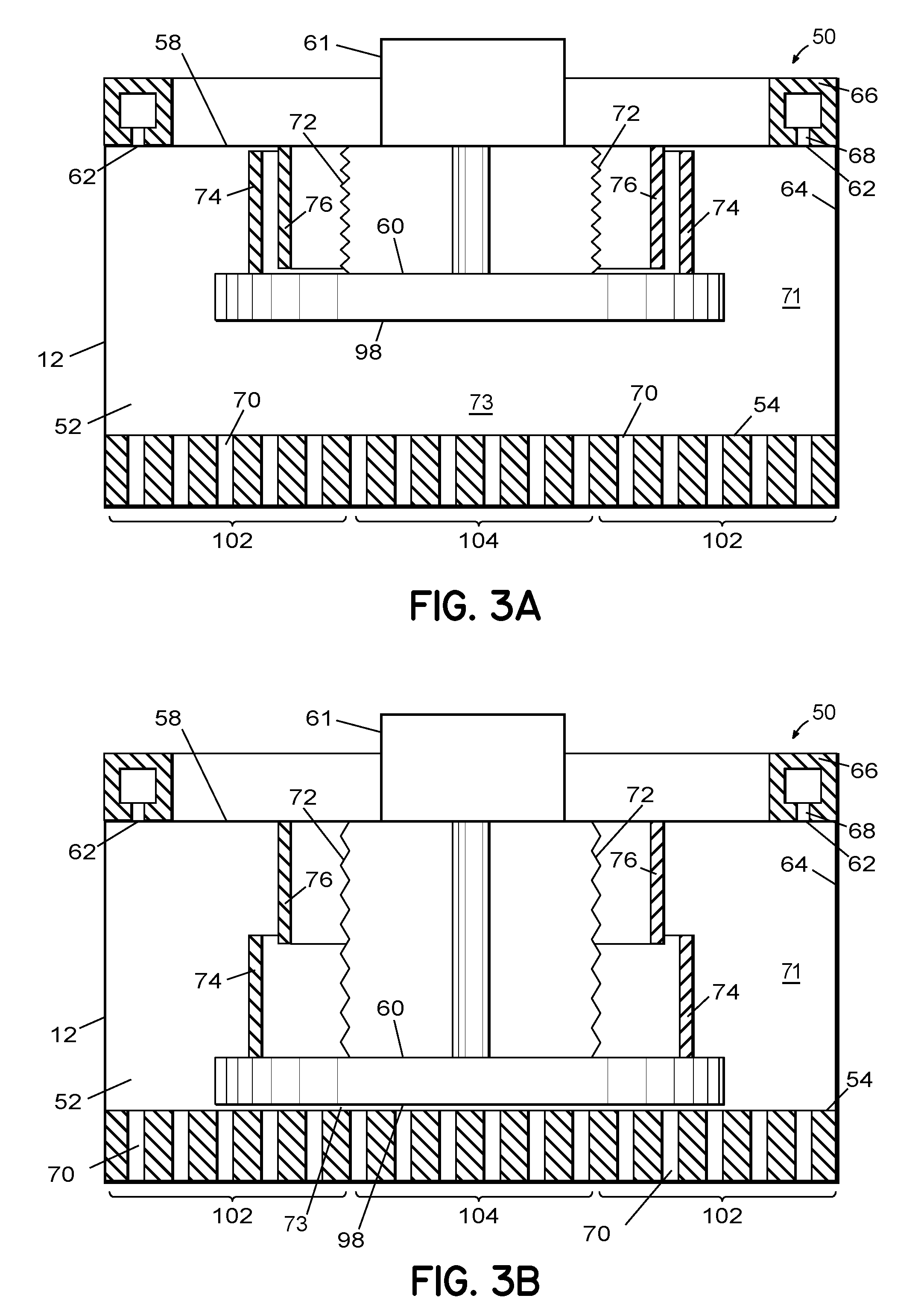
[0018]The invention is directed to use of a piston in the vapor distribution system of a chemical vapor deposition processing system for varying relative flow of a process gas through central and outer (edge) portions of a vapor distribution plate (showerhead) to achieve a desired uniformity in thickness of a deposited metal layer. According to one embodiment of the invention, the gas distribution system includes the vapor distribution plate coupled to a housing having an inlet and an outer circumferential edge, and a plenum located between the inlet and the vapor distribution pla...


PUM

PropertyMeasurementUnit
temperatureaaaaaaaaaa

Abstract

An apparatus and related method for distributing process gas in a vapor deposition system is described. The gas distribution system includes a vertically movable piston within its plenum, and the movement of the piston controls the flow rate of process gas through the vapor distribution plate of the gas distribution system. The piston can be used to accommodate changes in processing parameters that affect flow characteristics and to create edge-enhanced, uniform, and center-enhanced profiles of deposited material on a substrate without the need to replace the vapor distribution plate.

Description

BACKGROUND OF THE INVENTION[0001]1. Field of Invention[0002]The present invention relates to a method and system for thin film deposition, and more particularly to a system for improving the gas distribution of metal layers formed from metal precursors in uniform, center-enhanced, and edge-enhanced profiles.[0003]2. Description of Related Art[0004]The introduction of copper (Cu) metal into multilayer metallization schemes for manufacturing integrated circuits can necessitate the use of diffusion barriers / liners to promote adhesion and growth of the Cu layers and to prevent diffusion of Cu into the dielectric materials. Barriers / liners that are deposited onto dielectric materials can include refractive materials, such as tungsten (W), molybdenum (Mo), and tantalum (Ta), that are non-reactive and immiscible in Cu, and can offer low electrical resistivity. Current integration schemes that integrate Cu metallization and dielectric materials can require barrier / liner deposition processes...

Claims


Application Information

Patent Timeline
Patent Type & Authority Patents(United States)
IPC IPC(8): C23C16/455C23F1/00H01L21/306C23C16/06C23C16/22
CPCC23C16/45563C23C16/45587
Inventor VUKOVIC, MIRKO
Owner TOKYO ELECTRON LTD
Why Eureka
Try Eureka