Luminous keyboard

Inactive Publication Date: 2018-05-31
PRIMAX ELECTRONICS LTD
View PDF3 Cites 1 Cited by
  • Summary
  • Abstract
  • Description
  • Claims
  • Application Information

AI Technical Summary

Benefits of technology

This patent describes a luminous keyboard that solves the problem of light leaks. The keyboard has sheltering walls located where light leakage is likely to occur. These walls not only solve the problem but also improve the aesthetic appearance by shielding the light-guiding parts of the keyboard.

Problems solved by technology

However, the conventional luminous keyboard 2 still has some drawbacks.

Method used


Image

  • Luminous keyboard
  • Luminous keyboard
  • Luminous keyboard

Examples


Embodiment Construction

[0020]For overcoming the drawbacks of the conventional technology, the present invention provides a luminous keyboard.

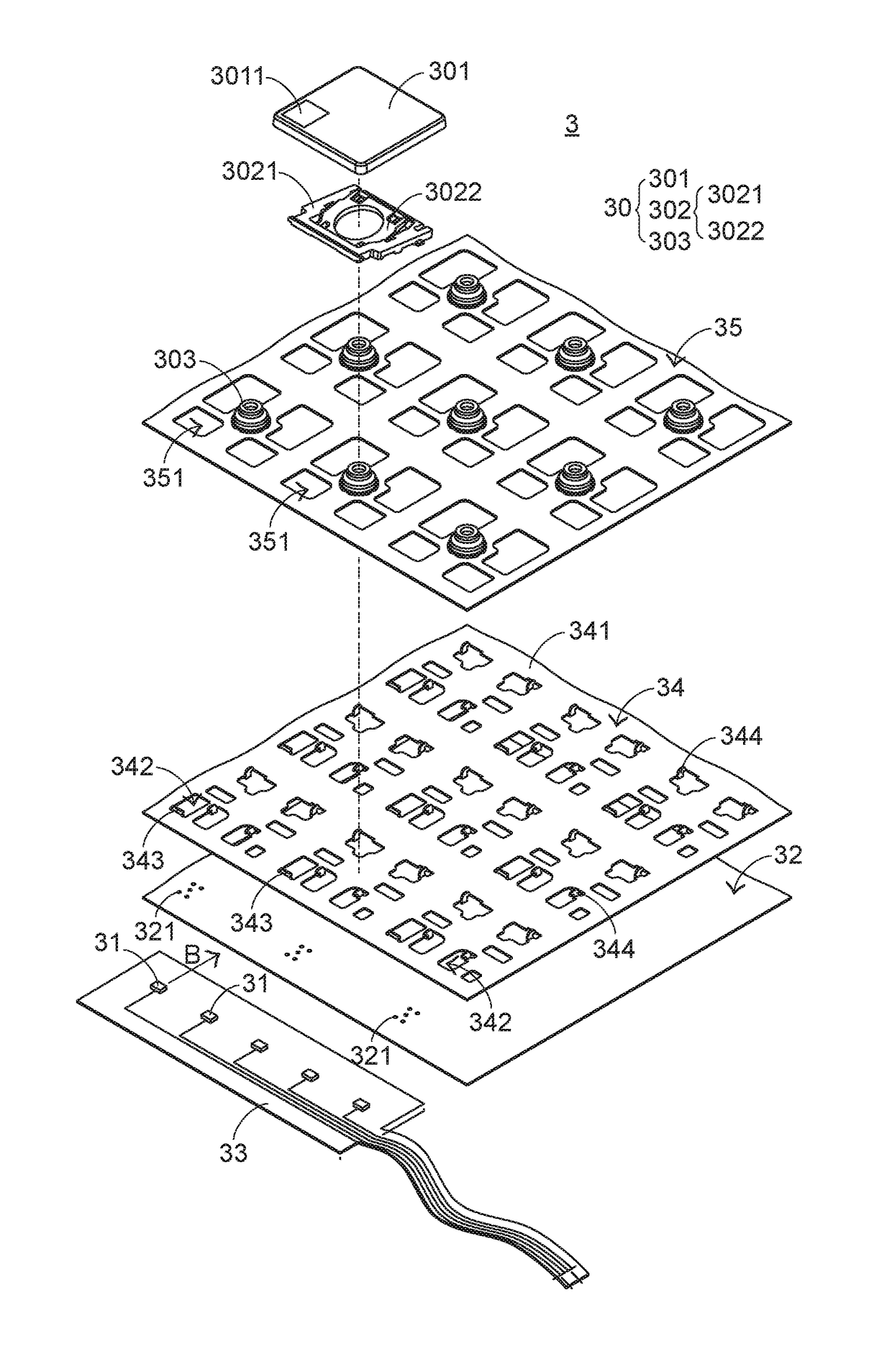
[0021]FIG. 3 is a schematic exploded view illustrating a portion of a luminous keyboard according to an embodiment of the present invention. As shown in FIG. 3, the luminous keyboard 3 comprises plural keys 30, plural light-emitting elements 31, a light guide plate 32, an illumination circuit board 33, a supporting plate 34 and a switch circuit board 35. The plural keys 30 are exposed outside the luminous keyboard 3. For succinctness, only one key 30 is shown in FIG. 3. Each key 30 comprises a keycap 301, a connecting element 302 and a triggering element 303. The plural light-emitting elements 31 are arranged below the plural keys 30 and disposed on the illumination circuit board 33. The plural light-emitting elements 31 emit plural light beams B. The light guide plate 32 is located under the plural keys 30 and arranged beside the plural light-emitting elements 31. T...


PUM


Abstract

A luminous keyboard includes plural keys, a light-emitting element, a light guide plate and a supporting plate. The light-emitting element emits light beams. The light guide plate includes plural light-guiding parts for guiding the light beams. The supporting plate includes a plate body, plural openings and plural sheltering walls. The openings run through the plate body and are aligned with the corresponding light-guiding parts. After the light beams are guided to pass through the openings by the light-guiding parts, the light beams are projected to the keys. The sheltering walls are disposed on the plate body and located beside the corresponding openings. The light beams and the light-guiding parts corresponding to the light beams are sheltered by the sheltering walls.

Description

FIELD OF THE INVENTION[0001]The present invention relates to a keyboard, and more particularly to a luminous keyboard with an illuminating function.BACKGROUND OF THE INVENTION[0002]Generally, the widely-used peripheral input device of a computer system includes for example a mouse device, a keyboard, a trackball device, or the like. Via the keyboard, characters and symbols can be inputted into the computer system directly. As a consequence, most users and most manufacturers of input devices pay much attention to the development of keyboards.[0003]FIG. 1 is a schematic top view illustrating the outer appearance of a conventional keyboard. As shown in FIG. 1, there are plural keys 10 on a surface of the conventional keyboard 1. These keys 10 are classified into several types, e.g. ordinary keys 101, numeric keys 102 and function keys 103. When one of these keys 10 is depressed by the user's finger, a corresponding signal is issued to the computer, and thus the computer executes a func...

Claims


Application Information

Patent Timeline
IPC IPC(8): H01H13/83F21V8/00H01H13/14
CPCH01H13/83H01H13/14G02B6/0091G02B6/0035G02B6/0021H01H3/125H01H2219/044H01H2219/056H01H2219/06H01H2219/064
Inventor CHIANG, YING-TE
Owner PRIMAX ELECTRONICS LTD
Why Eureka
Try Eureka