Method of splicing polarized films

Active Publication Date: 2013-11-28
TCL CHINA STAR OPTOELECTRONICS TECH CO LTD
View PDF17 Cites 2 Cited by
  • Summary
  • Abstract
  • Description
  • Claims
  • Application Information

AI Technical Summary

Benefits of technology

[0033]The method of splicing polarized films of the present invention is to make the side portions of two polarized films being overlapped with each other, then cut off the overlapped side portions and remove the separated parts, and perform flatten treatme

Problems solved by technology

Polarized-film rolls in the present market are limited in width (lower than 2 meters) due to the limitation of the manufacturing equipments, thus, if a manufacturer tends to produce liquid crystal display panels having widths larger than the width of the purchased polarized films (for example, larger than 2 meters), it is necessary for the manufacturer to splice the polarized films.
However

Method used


Image

  • Method of splicing polarized films
  • Method of splicing polarized films
  • Method of splicing polarized films

Examples


Embodiment Construction

[0036]The foregoing objects, features and advantages adopted by the present invention can be best understood by referring to the following detailed description of the preferred embodiments and the accompanying drawings. Furthermore, the directional terms described in the present invention, such as upper, lower, front, rear, left, right, inner, outer, side and etc., are only directions referring to the accompanying drawings, so that the used directional terms are used to describe and understand the present invention, but the present invention is not limited thereto.

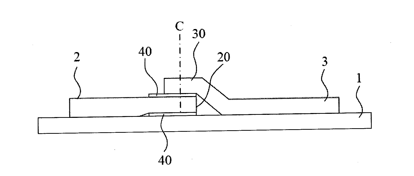
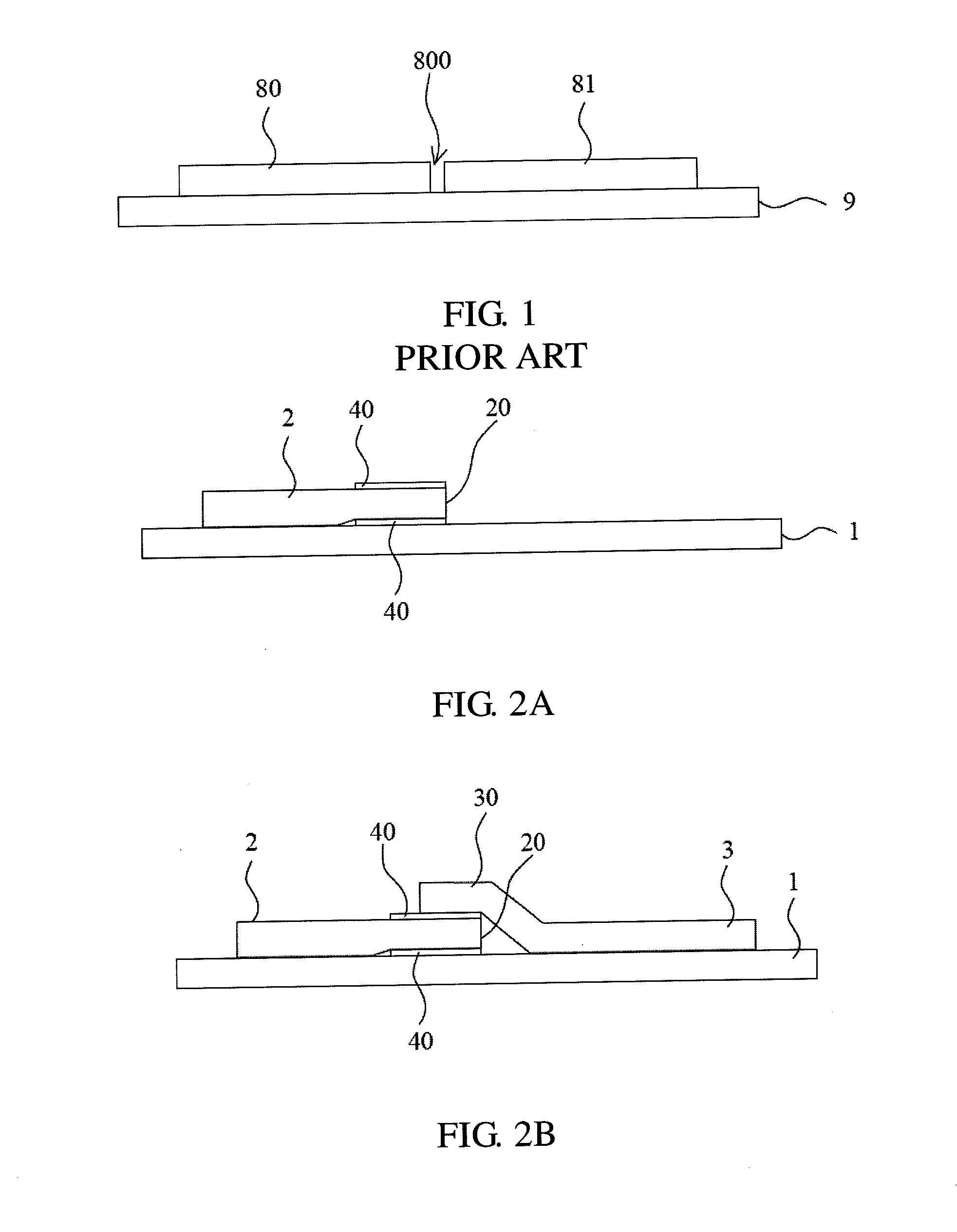
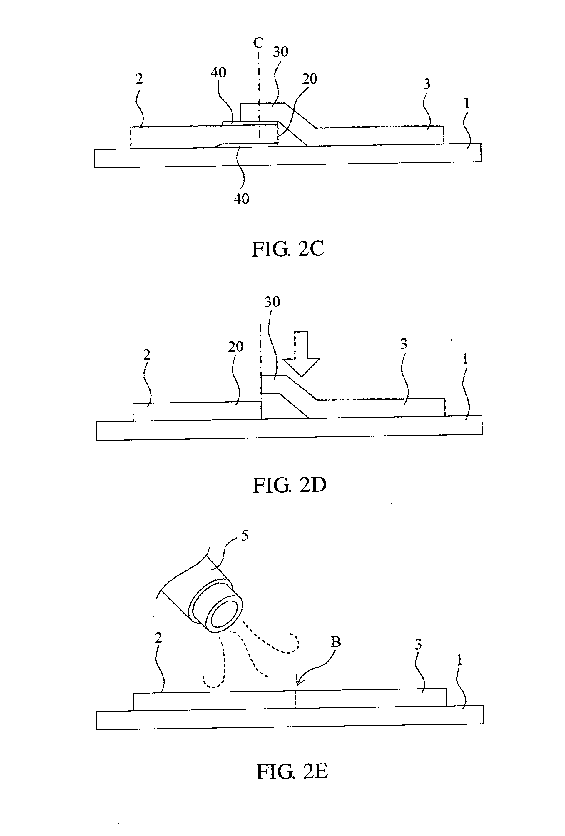
[0037]Please refer to FIGS. 2A to 2E, FIGS. 2A to 2E are schematic flow diagrams of a preferred embodiment of a method of splicing polarized films in accordance with the present invention. The method of splicing polarized films comprises steps as the following:

[0038]S100: providing a substrate 1;

[0039]S101: attaching a first polarized film 2 to the substrate 1;

[0040]S102: attaching a second polarized film 3 to the substrat...


PUM

PropertyMeasurementUnit
Lengthaaaaaaaaaa
Adhesivityaaaaaaaaaa

Abstract

The present invention discloses a method of splicing polarized films. The method includes steps of providing a substrate; attaching a first polarized film to the substrate; attaching a second polarized film to the substrate so that a side portion of the second polarized film is correspondingly overlapped with a side portion of the first polarized film; correspondingly cutting off the overlapped side portions of the first polarized film and the second polarized film; removing separated parts of the side portions from the first polarized film and the second polarized film; and performing a flatten treatment to the cut side portions of the first polarized film and the second polarized film. The method effectively reduces the interval between spliced polarized films so that the light leakage problem at the joint position is improved.

Description

BACKGROUND OF THE INVENTION[0001]1. Field of the Invention[0002]The present invention relates to a manufacturing technology of liquid crystal display device, especially to a method of splicing polarized films.[0003]2. Description of the Related Art[0004]Liquid crystal display device (LCD) has been widely used in all kinds of electronic products. Presently a liquid crystal display device mainly includes two transparent substrates, a liquid crystal layer mounted between the substrates and two polarized films respectively mounted on outer surfaces of the substrates.[0005]The polarized films are important components in a liquid crystal display device. When lights pass through one of the polarized films, the lights become polarized lights in the same polarization direction as the polarization axis of the polarized film. Liquid crystal molecules of the liquid crystal layer are controlled by an external electric filed and accordingly twist, thereby controlling whether the polarized lights ...

Claims


Application Information

Patent Timeline
IPC IPC(8): B32B38/10
CPCB29K2995/0034B29C63/02B29C2063/021B29C65/10B29C66/02241B29C66/1142B29C66/43B29C66/7338B29C2793/0027B29C2793/0081B29C66/8362Y10T156/1092Y10T156/108Y10T156/1066
Inventor HE, CHENGMINGCHENG, QUANXU, LIANGCAO, RONG
Owner TCL CHINA STAR OPTOELECTRONICS TECH CO LTD
Why Eureka
Try Eureka