Eureka AIR delivers breakthrough ideas for toughest innovation challenges, trusted by R&D personnel around the world.

Display device

a display panel and display angle technology, applied in non-linear optics, instruments, optics, etc., can solve the problems of reducing the light leakage phenomenon at the end portion of the display panel, the difference in the viewing angle has become disadvantageously increased, and the viewer may not clearly recognize the image at left or right sides, etc., to achieve the effect of improving the light leakage phenomenon and reducing the shear stress

Inactive Publication Date: 2016-03-24
SAMSUNG DISPLAY CO LTD
View PDF5 Cites 16 Cited by
  • Summary
  • Abstract
  • Description
  • Claims
  • Application Information

AI Technical Summary

Benefits of technology

The patent is about reducing a curved display panel's light leakage phenomenon caused by shear stress at the end points of the panel. The solution is to change the form of the fixing frame that supports and fixes the panel to reduce shear stress. This makes the display brighter and clearer at the end points.

Problems solved by technology

In recent years, as a screen size of the display device is increased, a viewing angle difference has become disadvantageously increased between cases where a viewer looks at a center portion; and left and right end portions of a screen.
That is, when an image displayed on a screen is viewed from a position corresponding to the center portion of a large display device, a viewer may clearly recognize an image at the center portion of the screen; however, the viewer may not clearly recognize images at left or right sides.
In particular, larger shear stress may occur at an end portion compared to a center portion, thereby causing light leakage at the end portions of the display panel.

Method used


Image

  • Display device
  • Display device
  • Display device

Examples


Embodiment Construction

[0035]Hereinafter, embodiments of the present disclosure of invention will be described in more detail with reference to the accompanying drawings.

[0036]Although the present invention can be modified in various manners and have several embodiments, specific embodiments are illustrated in the accompanying drawings and will be mainly described in the specification. However, the scope of the embodiments of the present invention is not limited to the specific embodiments and should be construed as including all the changes, equivalents, and substitutions included in the spirit and scope of the present invention.

[0037]Throughout the specification, when an element is referred to as being “connected” to another element, the element is “directly connected” to the other element, or “electrically connected” to the other element with one or more intervening elements interposed therebetween. It will be further understood that the terms “comprises,”“comprising,”“includes” and / or “including,” whe...


PUM

PropertyMeasurementUnit
heightaaaaaaaaaa
heightaaaaaaaaaa
distanceaaaaaaaaaa

Abstract

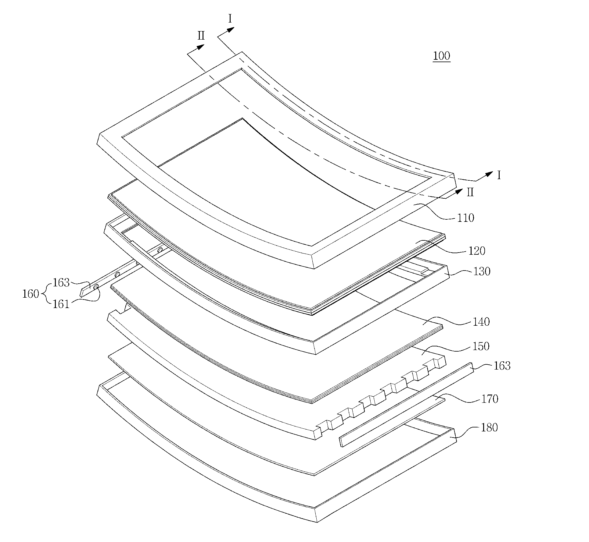
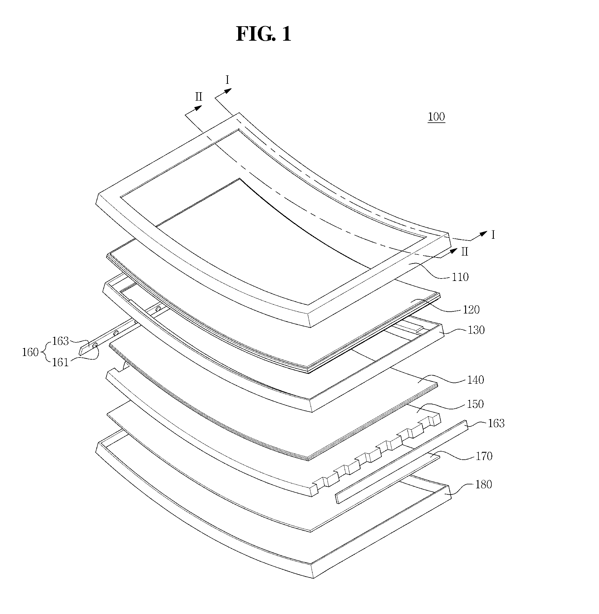
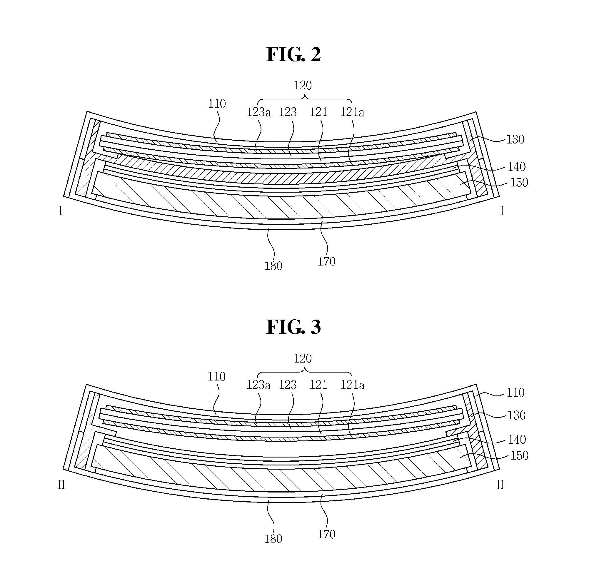
A display device includes: a display panel curved in one direction; and a middle frame supporting a lower edge portion of the display panel. The middle frame includes: a first support having a predetermined curvature; and a second support extending at a predetermined angle from the first support, the first support having a height difference at an end portion.

Description

CLAIM OF PRIORITY[0001]This application makes reference to, incorporates the same herein, and claims all benefits accruing under 35 U.S.C. §119 from an application earlier filed in the Korean Intellectual Property Office on 22 Sep. 2014 and there duly assigned Serial No. 10-2014-0125760.BACKGROUND OF THE INVENTION[0002]1. Field of the Invention[0003]Aspects of embodiments of the present invention relate to a display device including a frame configured to support and fix a display panel to have a constant curvature.[0004]2. Description of the Related Art[0005]Display devices are categorized into a liquid crystal display (LCD) device, an organic light emitting diode (OLED) display device, a plasma display panel (PDP), an electrophoretic display (EPD) device, and the like according to a light emitting method.[0006]In recent years, as a screen size of the display device is increased, a viewing angle difference has become disadvantageously increased between cases where a viewer looks at ...

Claims


Application Information

Patent Timeline
Patent Type & Authority Applications(United States)
IPC IPC(8): G02F1/1333
CPCG02F2001/133317G02F1/133308G02F1/133317
Inventor SHIN, JAI, KUKIM, HEE, GONAHN, SEONG, SIKLEE, KYOUNG, AHHWANG, TAE, KYOUNG
Owner SAMSUNG DISPLAY CO LTD
Why Eureka
Eureka Blog
Learn More