Thermal dissipation structure and method employing segmented heat sink surface coupling to an electronic component

a heat sink surface and heat dissipation structure technology, applied in semiconductor devices, cooling/ventilation/heating modifications, lighting and heating apparatus, etc., can solve problems such as interface fracturing, difficult use of solder or epoxy bonding attaching material, and increase the cost of heat dissipation, so as to facilitate the removal of heat from the electronic component, improve the thermal dissipation structure, and reduce the shear stress within the bond

Active Publication Date: 2006-08-01
INT BUSINESS MASCH CORP
View PDF15 Cites 34 Cited by
  • Summary
  • Abstract
  • Description
  • Claims
  • Application Information

AI Technical Summary

Benefits of technology

[0006]Therefore, a need exists for an enhanced thermal dissipation structure and method which allow a heat sink and electronic component of dissimilar materials with different coefficients of thermal expansion to be bonded together using an epoxy based or solder based attach material by reducing shear stresses within the bond.
[0007]The needs of the art are addressed, and additional advantages are provided, by the present invention which in one aspect is a thermal dissipation structure which includes a heat sink having a first surface configured to couple to a second surface of an electronic component for facilitating removal of heat from the electronic component. The first surface of the heat sink and the second surface of the electronic component are assumed to comprise dissimilar materials with different coefficients of thermal expansion. In accordance with an aspect of the invention, the first surface of the heat sink has a pattern of channels therein. The pattern of channels define multiple heat sink substructures. Each heat sink substructure includes a portion of the first surface of the heat sink, with the portions of the first surface of the heat sink substructures being coplanar and providing a reduced distance to neutral point across the first surface of the heat sink so that when the portions of the first surface of the heat sink are bonded to the second surface of the electronic component, shear stress within the bond is reduced.

Problems solved by technology

Applicants have discovered that problems arise when attempts are made to attach a graphite composite heat sink to, for example, a module cap or thermal spreader of an electronic component comprising a dissimilar material (e.g., a metal cap or spreader).
Because of an inherent coefficient of thermal expansion (CTE) mismatch between, for example, a graphite composite heat sink and a typical module cap or thermal spreader of an electronic component, and because of a relatively large distance to neutral point (DNP) of today's heat sinks, use of solder or an epoxy bonding attach material can be difficult (e.g., when DNP becomes greater than 40 mm).
This is because too much strain would be put on the bonded interface due to the CTE mismatch and the relatively large DNP, resulting in interface fracturing.

Method used


Image

  • Thermal dissipation structure and method employing segmented heat sink surface coupling to an electronic component
  • Thermal dissipation structure and method employing segmented heat sink surface coupling to an electronic component
  • Thermal dissipation structure and method employing segmented heat sink surface coupling to an electronic component

Examples


Embodiment Construction

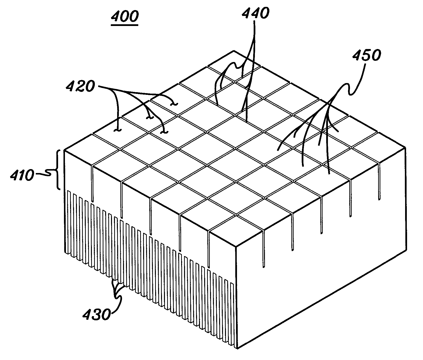
[0017]As used herein, “electronic component” comprises any heat generating component of, for example, a computer system or other electronics system requiring cooling. The term includes one or more integrated circuit devices, electronic devices, or electronic modules, either with or without a thermal cap or thermal spreader.

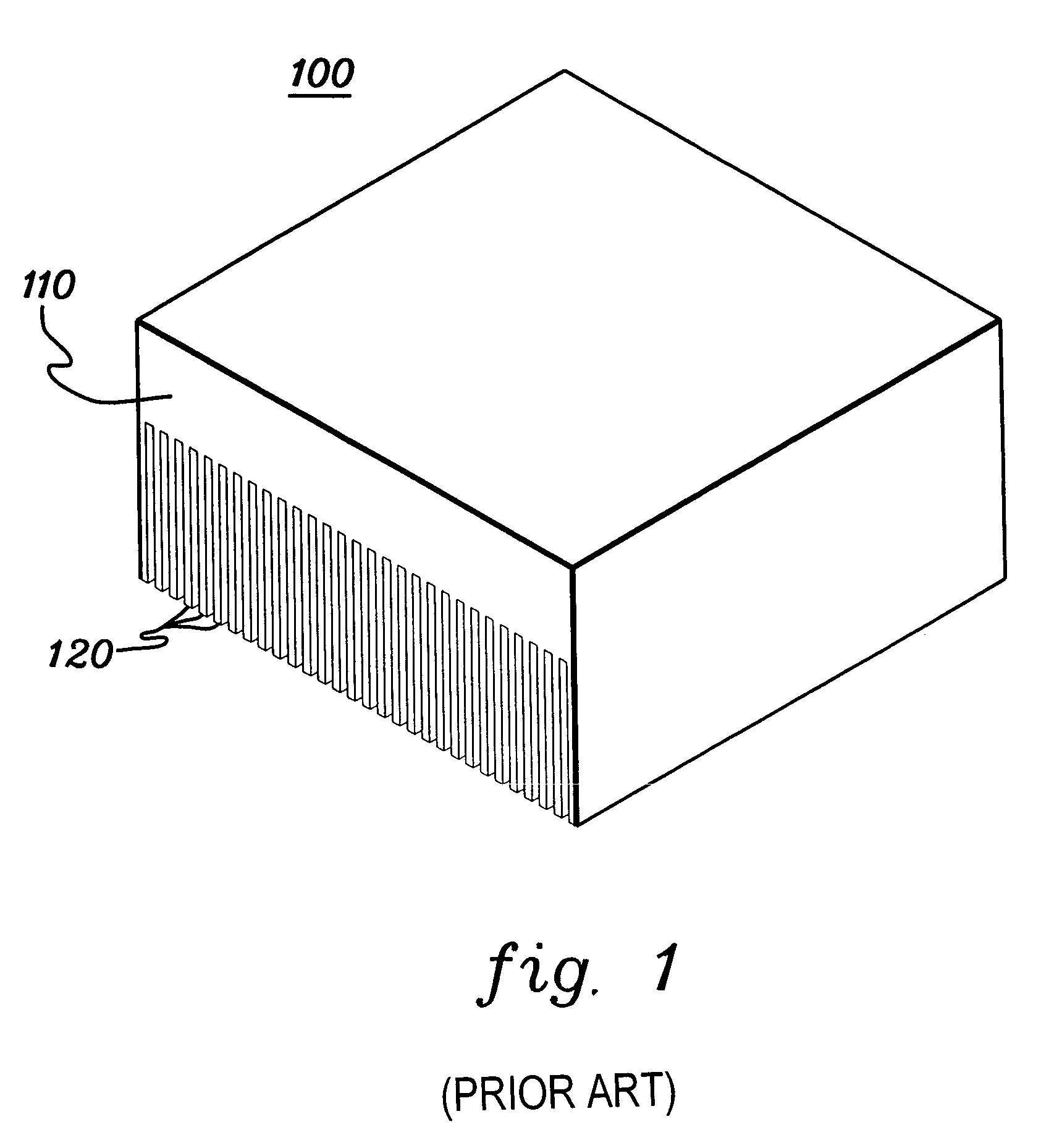
[0018]FIG. 1 depicts one embodiment of a conventional heat sink, generally denoted 100, for use with an electronic component. In this example, heat sink 100 is a monolithic structure which includes a base 110 from which a plurality of fin plates 120 extend to facilitate heat transfer from the heat sink to the surrounding environment. Typically heat sink 100 is made of aluminum (Al) or copper (Cu), both of which closely match the coefficient of thermal expansion of the electronic component surface to which the heat sink is to be attached (which is assumed to also comprise a metal).

[0019]As noted, certain advantages can be realized by transitioning the heat sink mat...


PUM


Abstract

A thermal dissipation structure and method are provided which include a heat sink having a surface configured to couple to a surface of an electronic component for facilitating removal of heat from the component. The heat sink surface and the electronic component surface comprise dissimilar materials with different coefficients of thermal expansion. The heat sink surface has a pattern of channels therein which define multiple heat sink substructures. Each heat sink substructure includes a portion of the heat sink surface. The portions of the heat sink surface are coplanar and provide a reduced distance to neutral point across the heat sink surface. When the portions of the heat sink surface are bonded to the electronic component surface, shear stress within the bond is reduced.

Description

TECHNICAL FIELD[0001]The present invention is directed to thermal dissipation structures and methods for removing heat from electronic components. More particularly, the present invention is directed to a thermal dissipation structure and method with enhanced bonding between a heat sink of the thermal dissipation structure and an electronic component, wherein the bonding surfaces of the heat sink and electronic component comprise dissimilar materials with different coefficients of thermal expansion.BACKGROUND OF THE INVENTION[0002]As an electronic component operates, heat is generated which must be removed or dissipated. Typically, heat is dissipated by a cooling structure, such as an aluminum (Al) or copper (Cu) heat sink coupled to the electronic component. The heat sink absorbs heat from the electronic component, and dissipates the heat via direct air convection. Heat sinks are well known in the electronics industry and are used extensively to dissipate heat generated by electron...

Claims


Application Information

Patent Timeline
Patent Type & Authority Patents(United States)
IPC IPC(8): H05K7/20F28F3/02H01L23/367
CPCF28F3/02H01L23/367H01L2924/0002H01L2924/00
Inventor CHU, RICHARD C.ELLSWORTH, JR., MICHAEL J.MAROTTA, EGIDIO E.SINGH, PRABJIT
Owner INT BUSINESS MASCH CORP
Why Eureka
Try Eureka