Thermoelectric heterostructure assemblies element

a heterostructure and heterostructure technology, applied in the field of thermoelectrics, can solve the problems of te materials, te materials, and difficult attachment of suitable thermal heat transfer members and electrodes to individual heterostructure assemblies, and achieve the effects of reducing shear stress, reducing power density, and reducing power density

Inactive Publication Date: 2011-04-26
ZT PLUS
View PDF159 Cites 34 Cited by
  • Summary
  • Abstract
  • Description
  • Claims
  • Application Information

AI Technical Summary

Benefits of technology

[0011]In one example, a bonding material is between the at least two heterostructure thermoelectric portions. The bonding material is advantageously configured to reduce the power density or the shear stress in the element, or both.
[0015]In this example, a bonding material may also be provided between the at least two layers. Advantageously, the layers and the bonding material are configured to reduce the power density of the thermoelectric. The layers and the bonding material may be configured to reduce shear stress as an alternative, or in addition to, reducing the power density.
[0016]An intermediate material may also be provided between at least one electrode and at least one layer of the thermoelectric material. Preferably, the intermediate material is also configured to reduce shear stress in the layers. In one configuration, the intermediate material is resilient.
[0020]Preferably, the layers and / or the bonding and / or intermediate materials are configured to decrease power density. One or another, or all, may be configured to reduce shear stress as well, and / or reducing the power density.

Problems solved by technology

The shape, dimensions and other geometrical characteristics of conventional heterostructures often make attachment of suitable thermal heat transfer members and electrodes to the individual heterostructures assembly difficult.
Further complications arise, in the extraction of thermal power from the structures.
New fabrication techniques are even more critical for systems made from thousands of segments since materials formed of many segments tend to be fragile and weakened by (1) internal stresses that result from fabrication, (2) the very nature of the materials and (3) internal weakness caused by contamination and process variation.
Further, certain TE materials, such as those based on Bismuth / Tellurium / Selenium mixtures, are inherently mechanically weak and hence, fragile in heterostructure form.

Method used


Image

  • Thermoelectric heterostructure assemblies element
  • Thermoelectric heterostructure assemblies element
  • Thermoelectric heterostructure assemblies element

Examples


Embodiment Construction

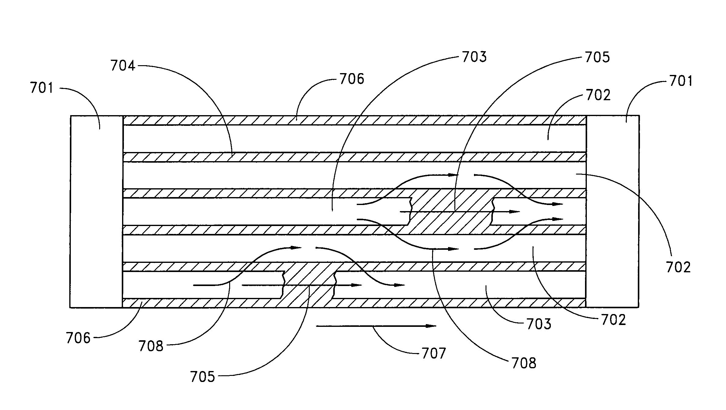
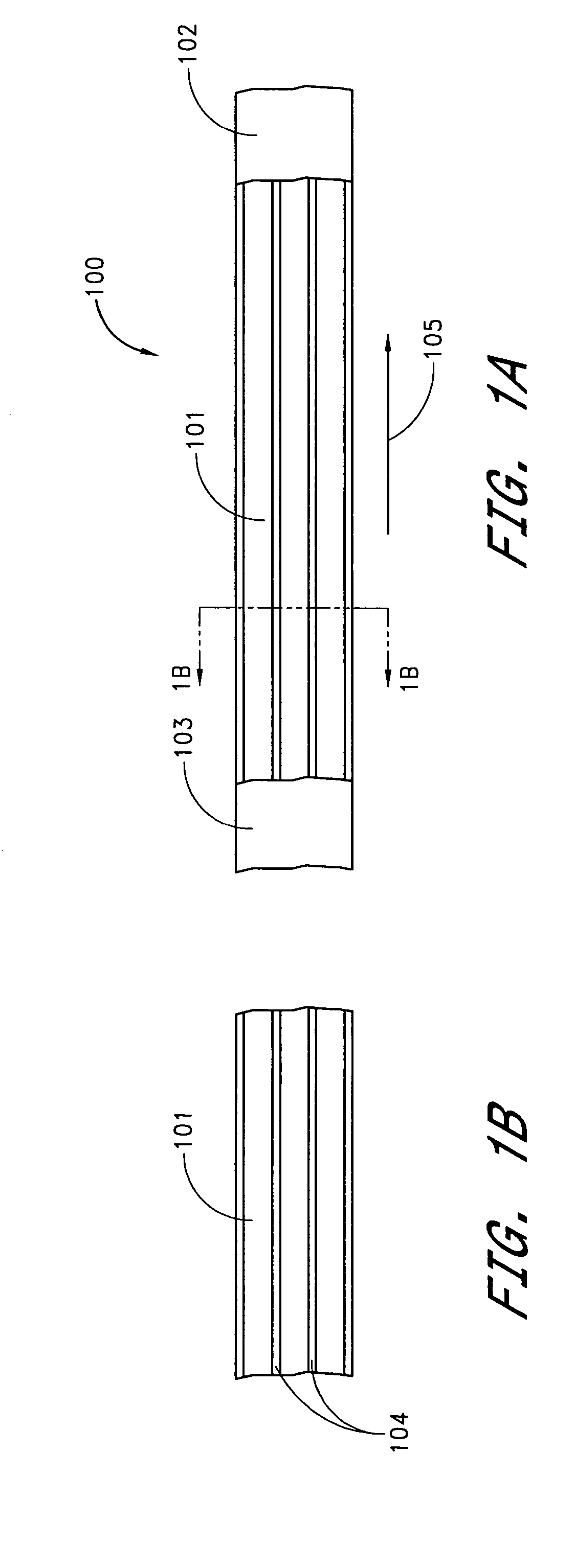
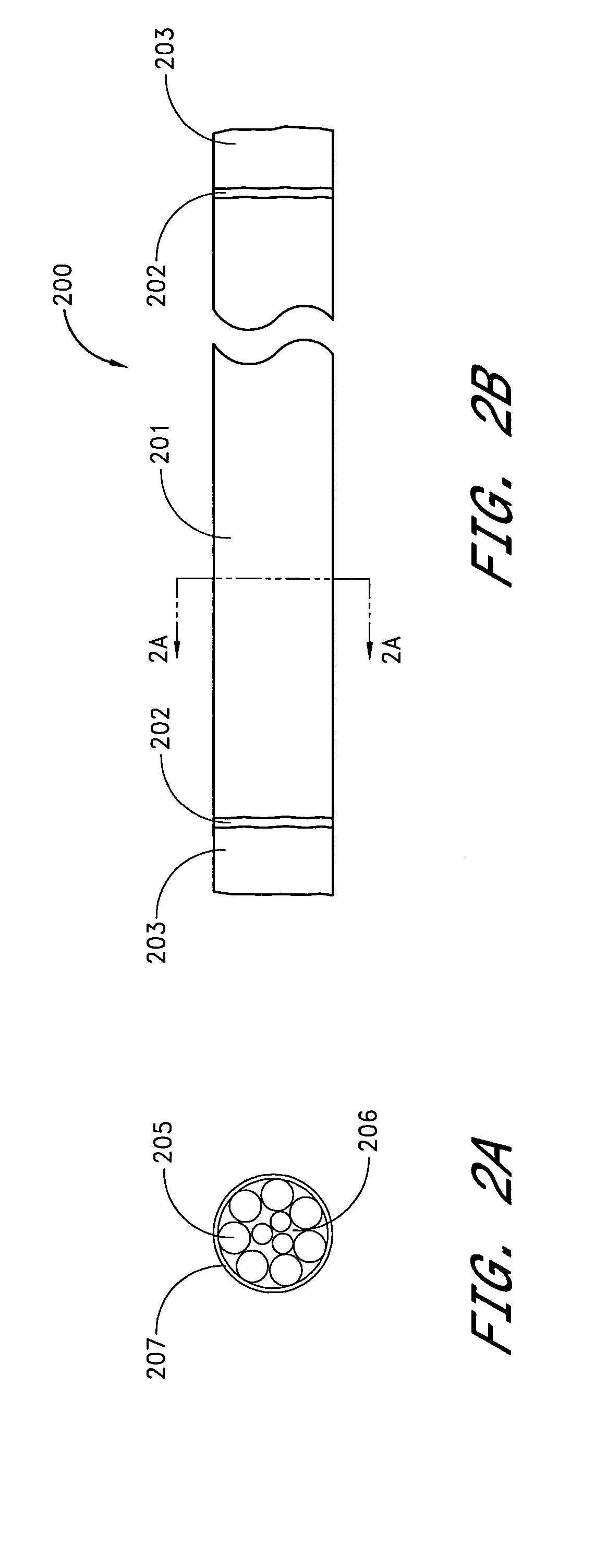
[0030]Several embodiments of thermoelectrics are disclosed where layers of heterostructure thermoelectric materials or thin layers of thermoelectric material form a thermoelectric element. Advantageously, the layers are of the same conductivity type (N-type or P-type) for each thermoelectric element. In one embodiment, the layers are of the same, or at least substantially the same, thermoelectric material. Where the layers are heterostructures, the heterostructures themselves may be formed of layers of thermoelectric material. The layers may be bound together with agents that improve structural strength, allow electrical current to pass in a preferred direction, and minimize adverse effects that might occur to the thermoelectric properties of the assembly by their inclusion. Fabrication of useful TE systems requires a careful understanding of the TE materials' individual properties, such as thermal conductivity, electrical conductivity, coefficient of thermal expansion, properties o...


PUM

PropertyMeasurementUnit
thermoelectricaaaaaaaaaa
conductivityaaaaaaaaaa
shear stressesaaaaaaaaaa

Abstract

Improved thermoelectric assemblies are disclosed, wherein layers of heterostructure thermoelectric materials or thin layers of thermoelectric material form thermoelectric elements. The layers are bound together with agents that improve structural strengths, allow electrical current to pass in a preferred direction, and minimize or reduce adverse affects, such a shear stresses, that might occur to the thermoelectric properties and materials of the assembly by their inclusion.

Description

CLAIM OF PRIORITY[0001]This application is a continuation of U.S. application Ser. No. 09 / 987,232, filed Nov. 6, 2001, now U.S. Pat. No. 6,812,395, which claims the benefit of U.S. Provisional Application No. 60 / 331,021, filed Oct. 24, 2001.BACKGROUND OF THE INVENTION [0002]1. Field of the Invention[0003]The following disclosure relates generally to thermoelectrics configured from heterostructures or thin layers of thermoelectric material to improve performance or usability of such thermoelectrics.[0004]2. Description of the Related Art[0005]The bulk properties of thermoelectric (TE) materials can be altered if the materials are formed from very thin films or segments of alternating materials. The resultant assemblies formed of segments of such thin films are usually called heterostructures. Each film segment is the order of tens to hundreds of angstroms thick. Since each segment is very thin, multiple segments are needed to fabricate cooling, heating and power generating devices. T...

Claims


Application Information

Patent Timeline
Patent Type & Authority Patents(United States)
IPC IPC(8): H01L35/08H01L37/00H01L35/00H01L35/28H01L35/30H01L35/34
CPCH01L35/34H01L35/08H10N10/817H10N10/01
Inventor BELL, LON E.
Owner ZT PLUS
Why Eureka
Try Eureka