
Electrosurgical apparatus and methods for treatment and removal of tissue

a tissue and electrosurgical technology, applied in the field of electrosurgical equipment and methods for treating and removing tissue, can solve the problems of tissue desiccation or destruction at the contact point with the patient's tissue, cell destruction, tissue damage or destruction, etc., and achieve the effect of convenient internal wetting, low current density, and large surface area

Inactive Publication Date: 2007-03-06
ARTHROCARE
View PDF252 Cites 317 Cited by
  • Summary
  • Abstract
  • Description
  • Claims
  • Application Information

AI Technical Summary

Benefits of technology

[0017]The apparatus may further include a supply or source of an electrically conductive fluid, and a fluid delivery element for delivering electrically conductive fluid to the electrode terminal(s) and the target site. The fluid delivery element may be located on the instrument, e.g., a fluid lumen or tube, or it may be part of a separate instrument. Alternatively, an electrically conductive gel or spray may be applied to the target site. In this embodiment, the apparatus may not have a fluid delivery element. In both embodiments, the electrically conductive fluid will preferably generate a current flow path between the active electrode(s) and one or more return electrode(s). In one embodiment, the return electrode is spaced a sufficient distance from the active electrode(s) to substantially avoid or minimize current shorting therebetween, and to shield the tissue at the target site from the return electrode .
[0019]In one configuration, the instrument includes a fluid delivery lumen for delivering electrically conductive fluid to the active and / or return electrodes, and an aspiration lumen for aspirating excess conductive fluid from the distal end of the apparatus or from the surgical site. In one embodiment, the fluid delivery and aspiration lumens create a fluid recirculation system for minimizing the amount of conductive fluid that contacts the patient, and for reducing the temperature to which a target tissue is exposed during a procedure.
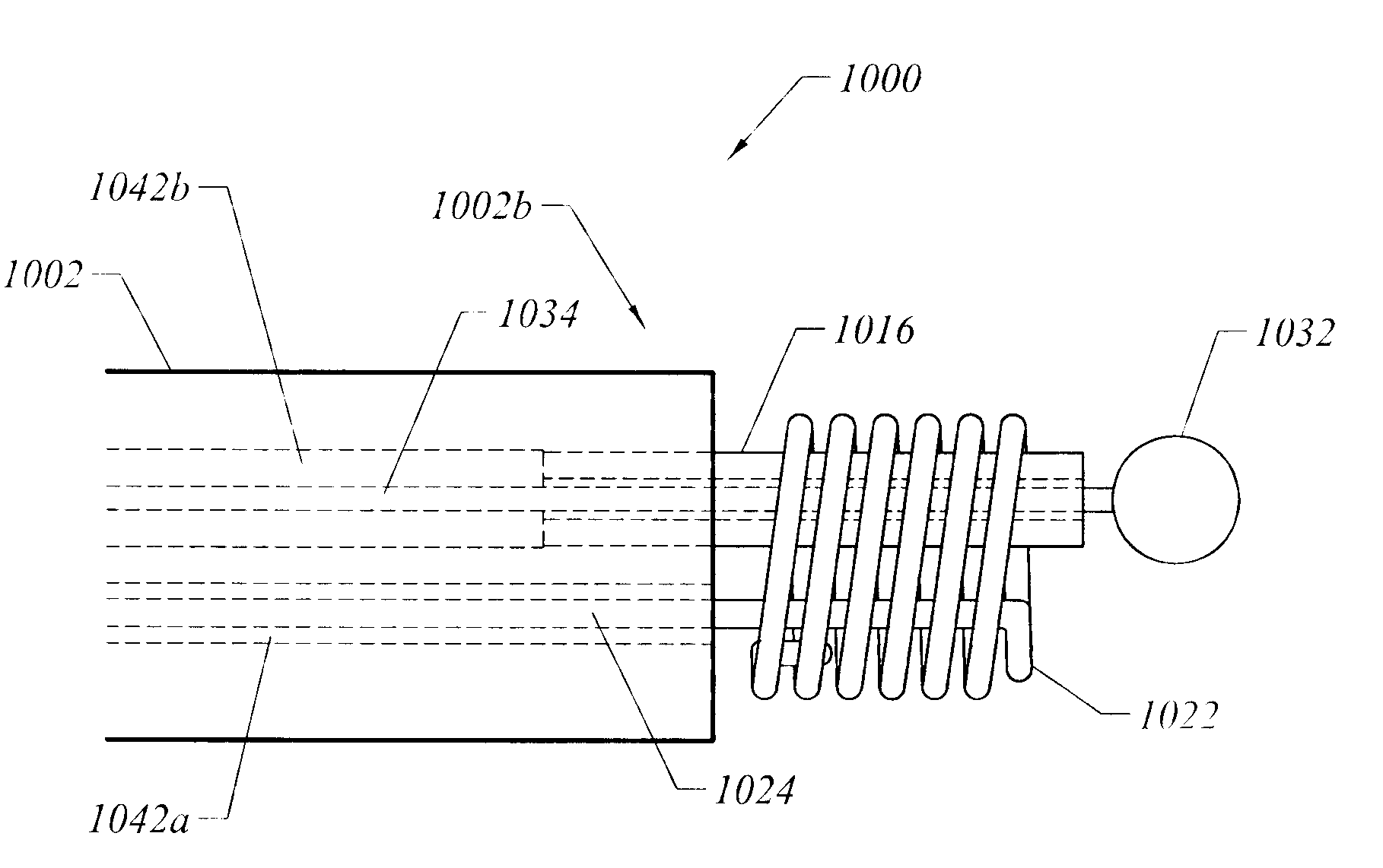
[0021]In an exemplary embodiment, a gap exists between each turn of the return electrode coil. The gaps between the turns of the return electrode coil facilitate wetting of the internal and external surfaces of the coil with an electrically conductive fluid delivered to the distal end of the shaft. The electrically conductive fluid delivered to the distal end of the shaft provides a current flow path between the active and return electrodes. The return electrode coil provides a relatively large surface area, and hence relatively low current densities, thereby decreasing the likelihood of inadvertent firing of the return electrode during treatment of a target tissue. Typically, the surface area of the return electrode coil is at least about twice (i.e., at least double, or 2×) the surface area of the active electrode head. More typically, the surface area of the return electrode coil is from about two times (2×) to about 20 times (20×) the surface area of the active electrode head. The active electrode head may be in the form of a hook, a metal disc, or a flattened coil.
[0022]In another aspect of the invention, there is provided an electrosurgical probe including an active electrode in the form of a flattened coil having from about 0.5 to 5 turns, preferably about 0.5 to 1.5 turns. In one embodiment, the active electrode includes a dividing portion disposed within an internal void of the active electrode coil, wherein the dividing portion at least partially spans the coil. In one embodiment, the dividing portion spans the coil of the active electrode, and divides the internal void within the coil into two portions. The presence of one or more voids within the coil promotes the retention of an electrically conductive fluid delivered to the coil. In one embodiment, the flattened coil has relatively sharp edges, which promote high current densities at the perimeter of the coil, thereby facilitating initiation and maintenance of a plasma in the presence of the electrically conductive fluid. The presence of a plasma at the perimeter of the active electrode coil promotes aggressive ablation and / or severing of target tissue via the molecular dissociation (vaporization) of tissue components.

Problems solved by technology

These traditional electrosurgical techniques for treatment have typically relied on thermal methods to rapidly heat and vaporize liquid within tissue and to cause cellular destruction.
This current, however, may inadvertently flow along localized pathways in the body having less impedance than the defined electrical path.
This situation will substantially increase the current flowing through these paths, possibly causing damage to or destroying tissue along and surrounding this pathway.
One drawback with this configuration, however, is that the return electrode may cause tissue desiccation or destruction at its contact point with the patient's tissue.
Another limitation of conventional bipolar and monopolar electrosurgery devices is that they are not suitable for the precise removal (i.e., ablation) of tissue.
At the point of contact of the electric arcs with tissue, rapid tissue heating occurs due to high current density between the electrode and tissue.
The tissue is parted along the pathway of evaporated cellular fluid, inducing undesirable collateral tissue damage in regions surrounding the target tissue site.
The use of electrosurgical procedures (both monopolar and bipolar) in electrically conductive environments can be further problematic.
However, the presence of saline, which is a highly conductive electrolyte, can cause shorting of the active electrode(s) in conventional monopolar and bipolar electrosurgery.
Such shorting causes unnecessary heating in the treatment environment and can further cause non-specific tissue destruction.
Conventional electrosurgical techniques used for tissue ablation also suffer from an inability to control the depth of necrosis in the tissue being treated.
The inability to control such depth of necrosis is a significant disadvantage in using electrosurgical techniques for tissue ablation, particularly in arthroscopic procedures for ablating and / or reshaping fibrocartilage, articular cartilage, meniscal tissue, and the like.
Despite these advantages, laser devices suffer from their own set of deficiencies.
In the first place, laser equipment can be very expensive because of the costs associated with the laser light sources.
Moreover, those lasers which permit acceptable depths of necrosis (such as excimer lasers, erbium:YAG lasers, and the like) provide a very low volumetric ablation rate, which is a particular disadvantage in cutting and ablation of fibrocartilage, articular cartilage, and meniscal tissue.
The holmium:YAG and Nd:YAG lasers provide much higher volumetric ablation rates, but are much less able to control depth of necrosis than are the slower laser devices.
The CO2 lasers provide high rate of ablation and low depth of tissue necrosis, but cannot operate in a liquid-filled cavity.
Such photo-dissociation reduces the likelihood of thermal damage to tissue outside of the target site.
Unfortunately, the pulsed mode of operation reduces the volumetric ablation rate, which may increase the time spent in surgery.

Method used


Image

  • Electrosurgical apparatus and methods for treatment and removal of tissue
  • Electrosurgical apparatus and methods for treatment and removal of tissue
  • Electrosurgical apparatus and methods for treatment and removal of tissue

Examples


Embodiment Construction

[0057]In the present invention, high frequency (RF) electrical energy is applied to one or more electrode terminals in the presence of electrically conductive fluid to remove and / or modify body tissue. The techniques of the present invention may be performed in a conventional open surgery environment or in a minimally invasive manner using cannulas, or port access devices. The present invention is useful in procedures where the tissue site is flooded or submerged with an electrically conductive fluid, such as arthroscopic surgery of the knee, shoulder, ankle, hip, elbow, hand or foot. Specifically, the present invention is useful in the resection and / or ablation of the meniscus and the synovial tissue within a joint during an arthroscopic procedure. In addition, tissues which may be treated by the system and method of the present invention include, but are not limited to, prostate tissue and leiomyomas (fibroids) located within the uterus, gingival tissues and mucosal tissues locate...


PUM


Abstract

Apparatus and methods for ablating, severing, cutting, shrinking, coagulating, or otherwise modifying a target tissue to be treated. In a method for treating a target tissue, an active electrode of an electrosurgical probe is positioned in at least close proximity to the target tissue in the presence of an electrically conductive fluid. A high frequency voltage is then applied between the active electrode and a return electrode, wherein, the high frequency voltage is sufficient to volumetrically remove (ablate), sever, or modify at least a portion of the target tissue. The probe comprises a multi-lumen shaft having a plurality of internal lumens, and a return electrode coil oriented substantially parallel to the shaft distal end. The active electrode may be in the form of a metal disc, a hook, or an active electrode coil. In the latter embodiment, the active electrode coil is typically arranged substantially orthogonal to the return electrode coil. Methods of making an active electrode coil, a return electrode coil, and an electrosurgical probe are also disclosed.

Description

RELATED APPLICATIONS[0001]The present application claims priority from U.S. Provisional Patent Application No. 60 / 299,094 filed Jun. 18, 2001 which is a continuation-in-part of U.S. patent application Ser. No. 09 / 586,295 filed Jun. 2, 2000, which is a division of U.S. patent application Ser. No. 09 / 248,763 filed Feb. 12, 1999, now U.S. Pat. No. 6,149,620, which derives priority from U.S. Provisional Application Nos. 60 / 096,150 and 60 / 098,122, filed Aug., 11, 1998 and Aug., 27, 1998, respectively, and U.S. patent application Ser. No. 08 / 795,686, filed Feb. 5, 1997, now U.S. Pat. No. 5,871,469, which is a continuation of U.S. Pat. No. 5,697,882, filed Nov. 22, 1995, the complete disclosures of which are incorporated herein by reference for all purposes.[0002]The present invention is related to commonly assigned U.S. patent applications Ser. No. 09 / 177,861, filed Oct. 23, 1998, now U.S. Pat. No. 6,066,134, application Ser. No. 08 / 977,845, filed Nov. 25, 1997, now U.S. Pat. No. 6,210,40...

Claims


Application Information

Patent Timeline
Patent Type & Authority Patents(United States)
IPC IPC(8): A61B17/20A61B18/14
CPCA61B18/148A61B18/1492A61B18/042A61B2018/1472A61B2018/00583A61B2018/1213A61B2018/1437A61B2018/00577
Inventor DAHLA, ROBERT H.WOLOSZKO, JEAN
Owner ARTHROCARE
Learn More