Display device

a display device and display screen technology, applied in non-linear optics, instruments, optics, etc., can solve the problem that the above design is not suitable for the narrow border design, and achieve the effect of improving light leakage or shadow issue, and structural strength

Active Publication Date: 2018-04-26
INNOLUX CORP
View PDF6 Cites 15 Cited by
  • Summary
  • Abstract
  • Description
  • Claims
  • Application Information

AI Technical Summary

Benefits of technology

[0005]An objective of the present disclosure is to provide a display device that can achieve the narrow border design, provide a sufficient structural strength, or improve the light leakage or shadow issue at the edge of the active area.
[0008]As mentioned above, in the display device of this disclosure, the supporting frame includes a first supporting portion, and the optical film assembly is partially disposed between the first supporting portion and the display panel. In addition, the light-penetrated adhesive member is disposed between the first supporting portion of the supporting frame and the optical film assembly. The light-penetrated adhesive member includes a first portion disposed corresponding to the non-pixel region and a second portion disposed corresponding to the pixel region. Moreover, the supporting frame is light penetrated. Moreover, the connecting circuit board includes a reflective surface disposed corresponding to a side surface of the supporting frame. Compared with the conventional technology, the structural design of this disclosure can achieve the narrow border design, provide a sufficient structural strength, or improve the light leakage or shadow issue at the edge of the active area.

Problems solved by technology

However, the above design is not suitable for the narrow border design (e.g. the border is equal to or less than 1 mm).

Method used


Image

  • Display device
  • Display device
  • Display device

Examples


Embodiment Construction

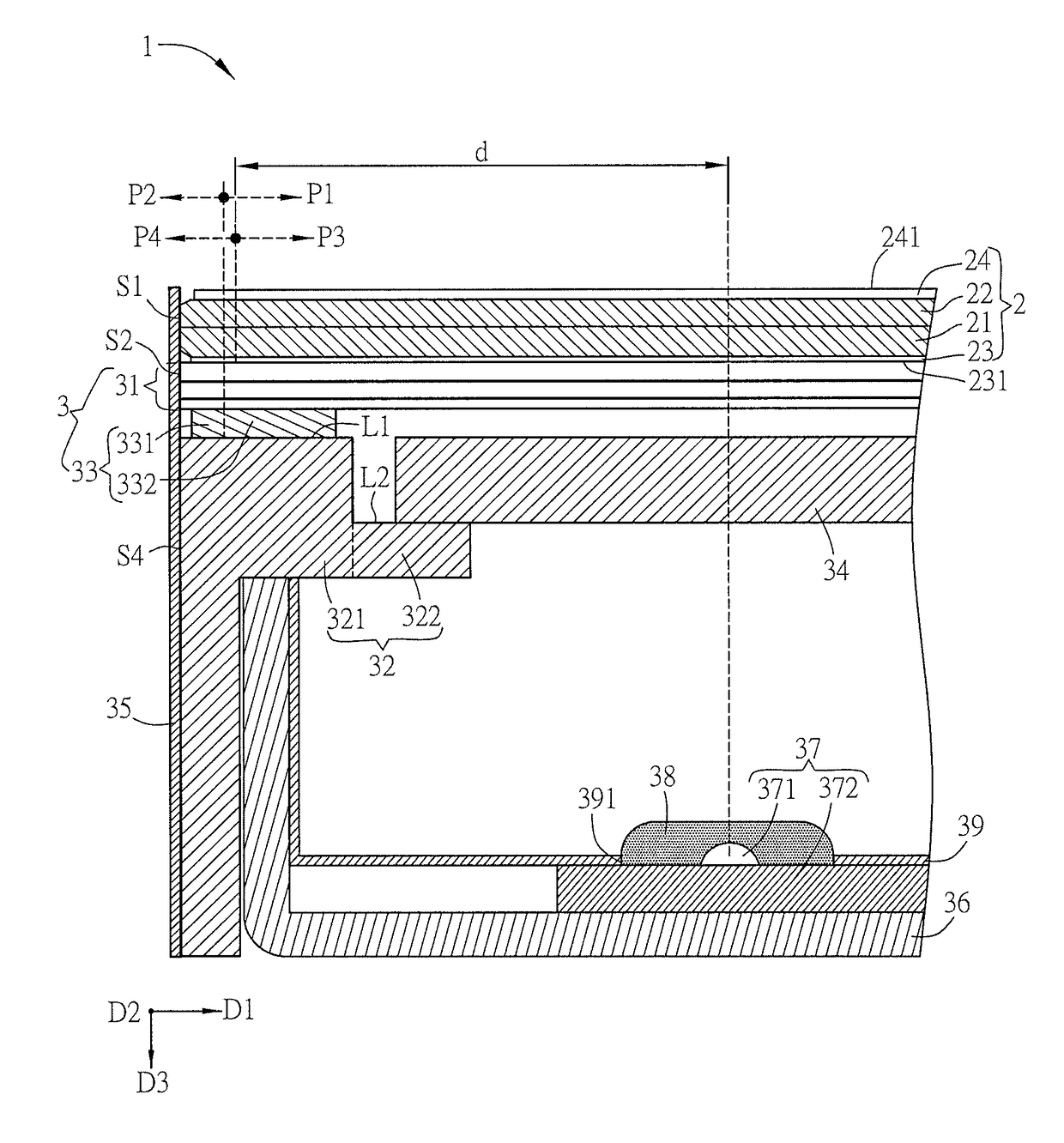
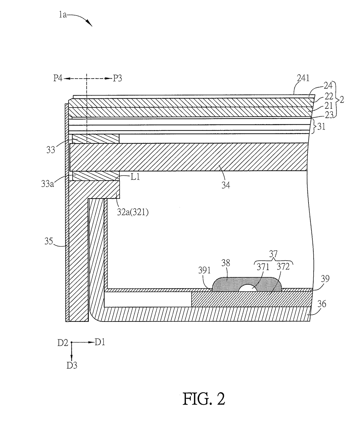
[0013]The embodiments of the disclosure will be apparent from the following detailed description, which proceeds with reference to the accompanying drawings, wherein the same references relate to the same elements. Moreover, the drawings of all implementation are schematic, and they do not mean the actual size and proportion. The terms of direction recited in the disclosure, for example up, down, left, right, front, or rear, only define the directions according to the accompanying drawings for the convenience of explanation but not for limitation. In addition, if one element is formed on, above, under, or below another element, these two elements can be directly contacted with each other or not directly contacted with each other but have an addition element disposed therebetween. The names of elements and the wording recited in the disclosure all have ordinary meanings in the art unless otherwise stated. Therefore, a person skilled in the art can unambiguously understand their meani...


PUM

PropertyMeasurementUnit
transmittanceaaaaaaaaaa
widthaaaaaaaaaa

Abstract

A display device includes a supporting frame, a display panel, an optical film assembly, and a light-penetrated adhesive member. The supporting frame includes a first supporting portion, and the display panel is disposed on the supporting frame. The display panel includes a pixel region and a non-pixel region, and the non-pixel region is disposed outside of the pixel region. The optical film assembly is partially disposed between the first supporting portion and the display panel. The light-penetrated adhesive member is disposed between the first supporting portion of the supporting frame and the optical film assembly. The light-penetrated adhesive member includes a first portion disposed corresponding to the non-pixel region and a second portion disposed corresponding to the pixel region. The configuration can achieve the narrow border design, provide a sufficient structural strength, or improve the light leakage or shadow issue at the edge of the active area.

Description

CROSS REFERENCE TO RELATED APPLICATIONS[0001]This Non-provisional application claims priority under 35 U.S.C. § 119(a) on Patent Application No(s). 201610912775.5 filed in People's Republic of China on Oct. 20, 2016, the entire contents of which are hereby incorporated by reference.BACKGROUNDTechnical Field[0002]The present disclosure relates to a display device and, in particular, to a display device with a narrow border design.Related Art[0003]With the development of technologies, flat display devices have been widely applied to various fields. Due to the advantages such as low power consumption, less weight, compact size and less radiation, the liquid crystal display (LCD) devices have gradually replaced the traditional cathode ray tube (CRT) display devices and been applied to various electronic products, such as mobile phones, portable multimedia devices, notebook computers, liquid crystal TVs and liquid crystal screens.[0004]Regarding the structure of the conventional LCD modu...

Claims


Application Information

Patent Timeline
Patent Type & Authority Applications(United States)
IPC IPC(8): G02F1/1333G02F1/1335
CPCG02F1/133308G02F1/133553G02F1/133528G02F2001/133317G02F1/133606G02F2202/28G02F1/133317
Inventor CHEN, YIN-LINKUO, TSU-CHIHSU, YU-KAIYEN, JEN-HSIANG
Owner INNOLUX CORP
Why Eureka
Try Eureka