Buried device identifier fill and method of identifying a burried device using the device identifier fill

a technology of buried devices and identification fills, which is applied in the direction of cables, underground tubes, mechanical equipment, etc., can solve the problems of not being able to use the current vacuum system, waste of many hours dumping spoil from the trailer, and inability to use the conventional device for trenching and laying cables or ducts continuously

Inactive Publication Date: 2018-06-07
CCIIP LLC
View PDF7 Cites 22 Cited by
  • Summary
  • Abstract
  • Description
  • Claims
  • Application Information

AI Technical Summary

Problems solved by technology

Conventional devices for the trenching and laying cable or duct cannot be used continuously.
However, many hours are wasted by having to dump the spoil from the trailers.
While the Vacuum truck concept is known in the industry, there is no current vacuum system that allows one to use a second vacuum or one vacuum to expel the cutting spoils into a cement / zim mixer or container allowing for the material to be recycled.
Installing new optical fiber networks to a location is expensive and time consuming.
Construction often inadvertently destroys buried devices, such as water, sewer, power, and telecommunications devices.

Method used


Image

  • Buried device identifier fill and method of identifying a burried device using the device identifier fill
  • Buried device identifier fill and method of identifying a burried device using the device identifier fill
  • Buried device identifier fill and method of identifying a burried device using the device identifier fill

Examples


Embodiment Construction

[0038]In the following description, for purposes of explanation and not limitation, specific details are set forth, such as particular networks, communication systems, computers, terminals, devices, components, techniques, data and network protocols, software products and systems, operating systems, development interfaces, hardware, etc. in order to provide a thorough understanding of the present invention with reference to the attached non-limiting Figures.

[0039]However, it will be apparent to one skilled in the art that the present invention may be practiced in other embodiments that depart from these specific details. Detailed descriptions of well-known networks, communication systems, computers, terminals, devices, components, techniques, data and network protocols, software products and systems, operating systems, development interfaces, and hardware are omitted so as not to obscure the description.

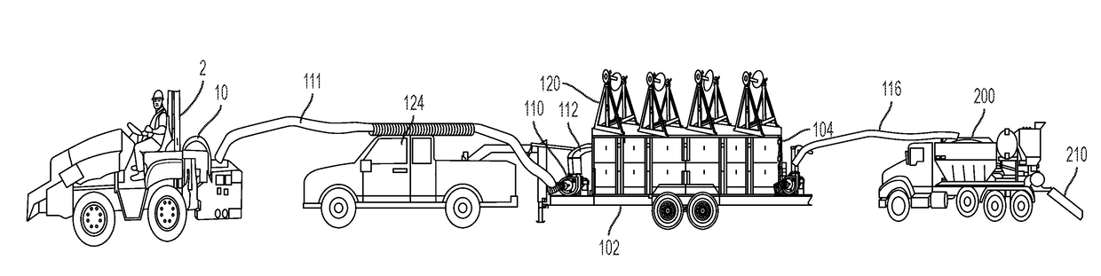
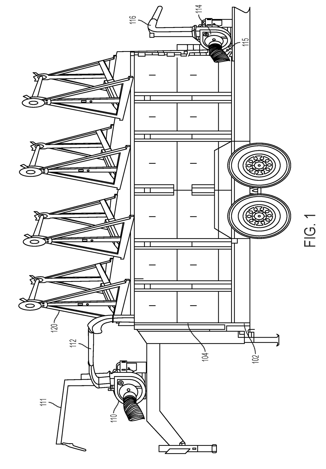
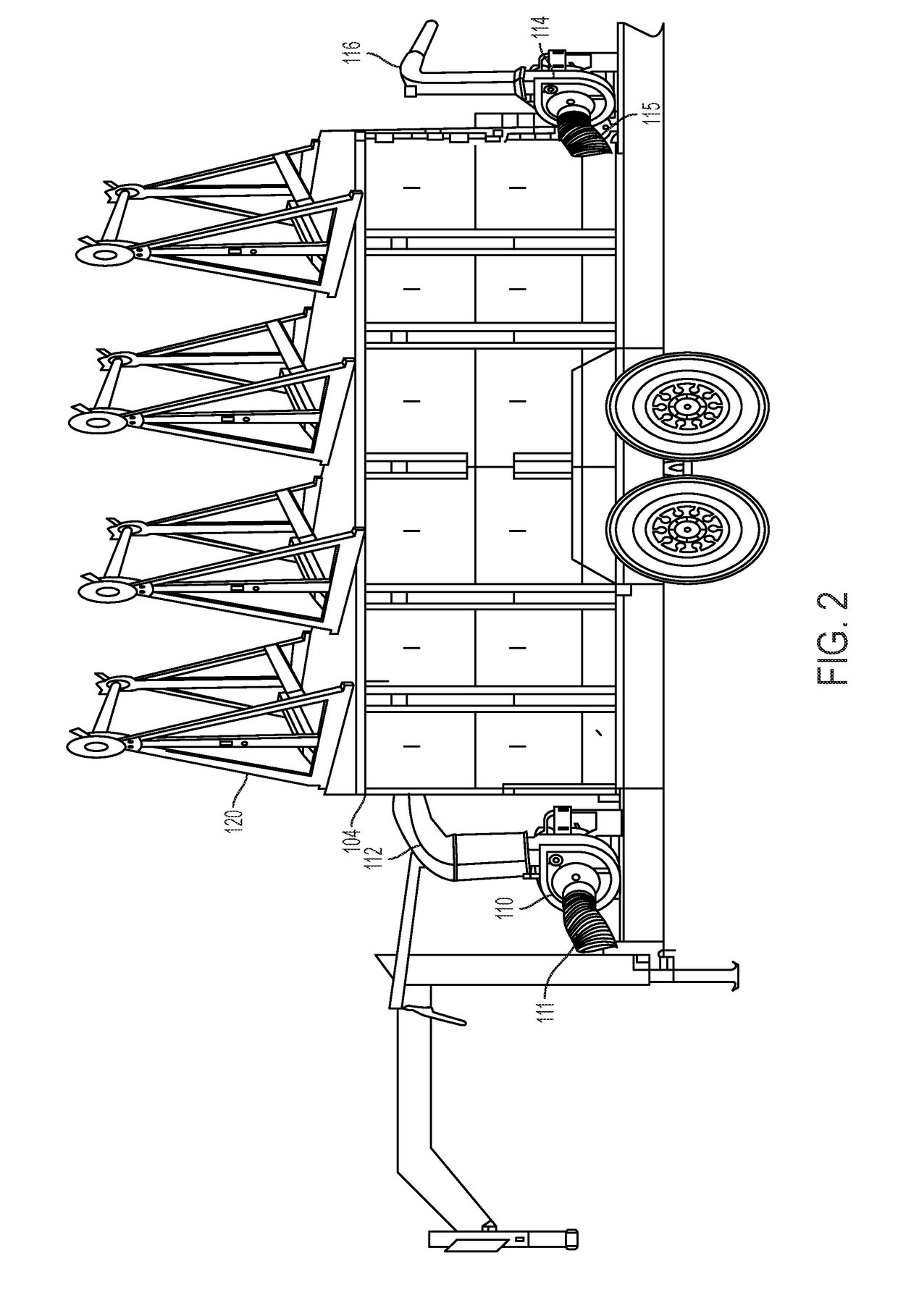
[0040]As shown in FIGS. 1-4, the multifunctional reel carrier, spoil material ha...


PUM


Abstract

Provided is a method of identifying a location and/or type of buried device by a device identifier fill covering the buried device. Also provided is a buried device under the device identifier fill.

Description

FIELD OF THE INVENTION[0001]The invention generally relates to a buried device identifier and a method of identifying a buried device using the device identifier fill.BACKGROUND OF THE INVENTION[0002]Conventional devices for the trenching and laying cable or duct cannot be used continuously. The micro trencher saw usually creates a pile of spoil (dirt, asphalt, concrete, etc.) alongside the formed trench and the trench must be cleaned before laying the cable in the trench. The pile of spoil must then be removed. A fill, also referred to as cement or grout, is inserted into the trench on top of the cable or innerduct / microduct. Large industrial vacuum trailers have been used to remove the piled up spoil. However, many hours are wasted by having to dump the spoil from the trailers.[0003]There is a great need for a device that can be used to continuously remove and in some instances recycle the spoil to in effort to increase the speed for placing the cable and / or innerduct / microduct an...

Claims


Application Information

Patent Timeline
Patent Type & Authority Applications(United States)
IPC IPC(8): F16L1/11E02F5/10E02F5/12F16L1/028H02G1/06H02G9/02H02G9/06
CPCF16L1/11E02F5/10E02F5/12F16L1/028H02G1/06H02G9/02H02G9/06H02G9/025E02F5/08E02F5/101E02F5/226E02F9/245
Inventor PINO, ANGELO J.URBAN, DANIEL
Owner CCIIP LLC
Why Eureka
Try Eureka