Door lock system coupled to an image capture device
Active Publication Date: 2018-06-28
AUGUST HOME
View PDF7 Cites 35 Cited by
Summary
Abstract
Description
Claims
Application Information
AI Technical Summary
This helps you quickly interpret patents by identifying the three key elements:
Problems solved by technology
Method used
Benefits of technology
Benefits of technology
[0014]A further object of the present invention is to provide a wireless acce
Problems solved by technology
Such a latch by itself is often easy to improperly depress-release by an unauthorized person, with a card-type element or even a pry bar.
However, if a person forgets to so actuate the deadbolt, either manually with an inner hand turn when inside, or by a key outsid
Method used
Image
Click on the blue label to locate the original text in one second.
Reading with bidirectional positioning of images and text.
Examples
Embodiment Construction
[0053]As used herein, the term engine refers to software, firmware, hardware, or other component that can be used to effectuate a purpose. The engine will typically include software instructions that are stored in non-volatile memory (also referred to as secondary memory). When the software instructions are executed, at least a subset of the software instructions can be loaded into memory (also referred to as primary memory) by a processor. The processor then executes the software instructions in memory. The processor may be a shared processor, a dedicated processor, or a combination of shared or dedicated processors. A typical program will include calls to hardware components (such as I / O devices), which typically requires the execution of drivers. The drivers may or may not be considered part of the engine, but the distinction is not critical.
[0054]As used herein, the term database is used broadly to include any known or convenient means for storing data, whether centralized or di...
PUM
Abstract
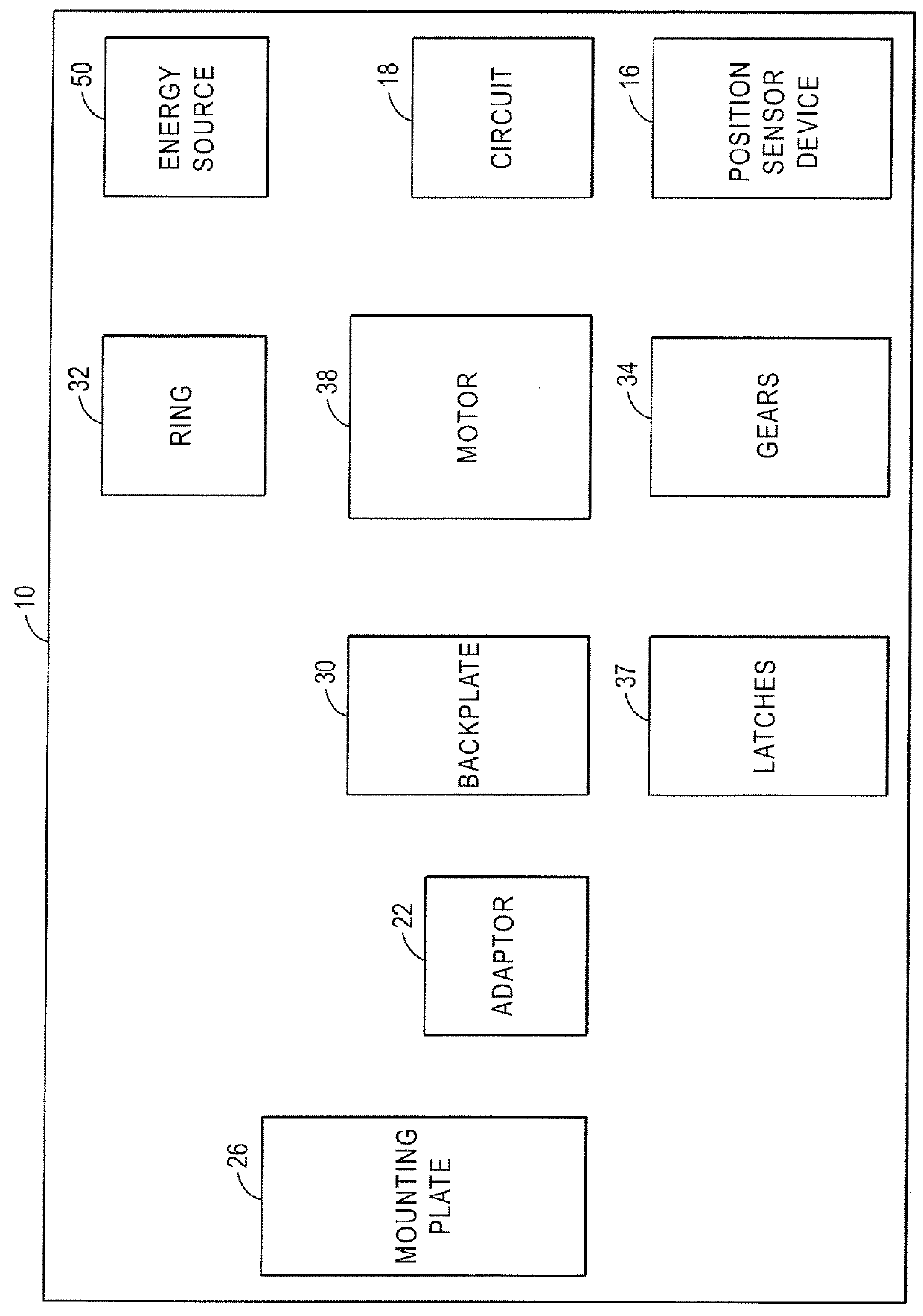
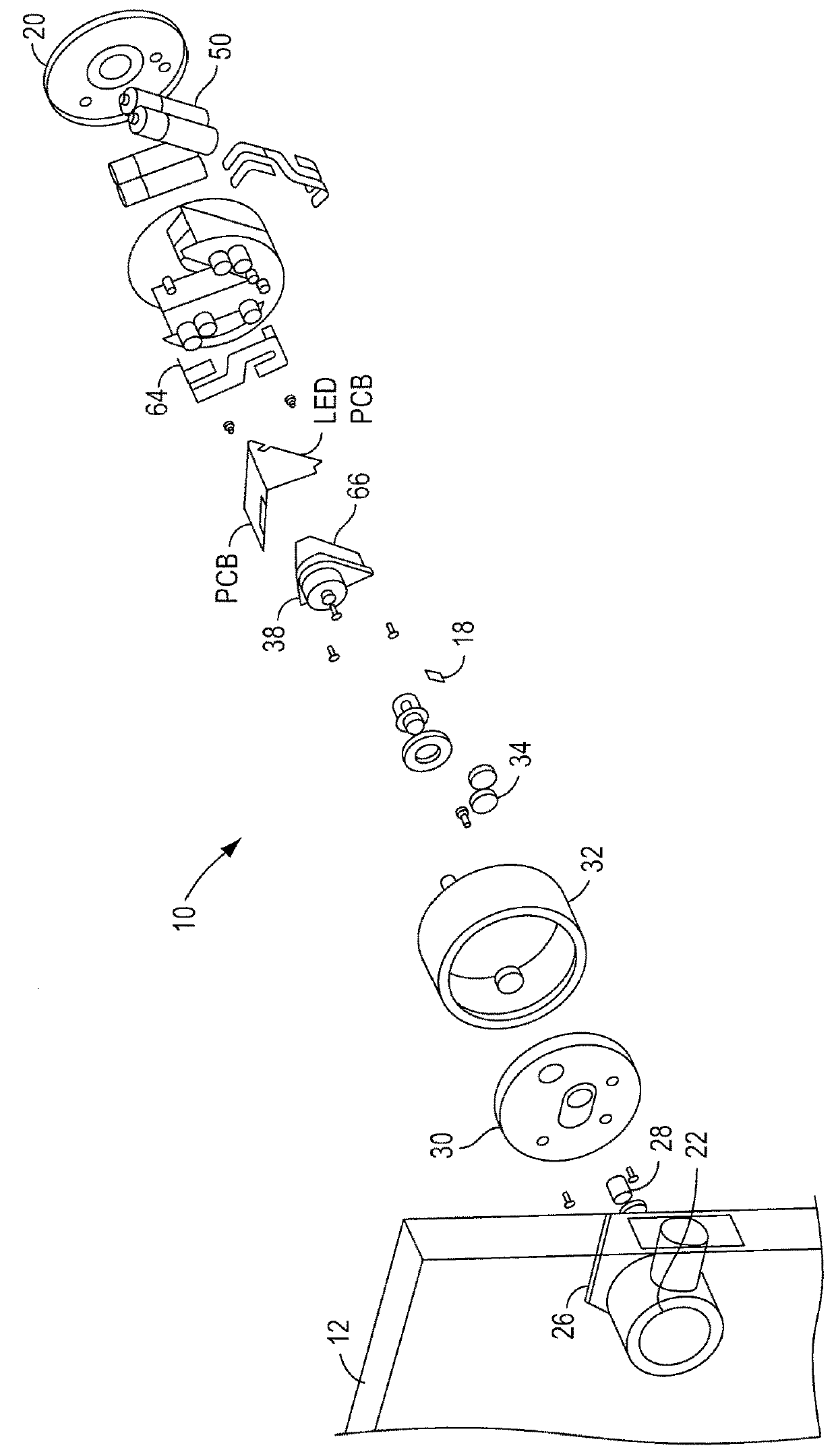
A wireless access system at a building is provided. A door lock system includes: a lock status device configured to be coupled to the drive shaft of a lock device, the lock status device assisting in locking and unlocking a lock of a lock device. A processor is coupled to the door lock system. An image capture device at the building is configured to be in communication with the door lock system and capture an image of an object in the vicinity of the building. A light source assembly is in communication with the image capture device.
Description
CROSS-REFERENCE TO RELATED APPLICATIONS[0001]This application claims the priority benefit of all of the following: a continuation of Ser. No. 15 / 867,992, filed Jan. 11, 2018, which is a continuation in part of Ser. No. 15 / 867,773, filed Jan. 11, 2018, which is a Continuation in part of Ser. No. 15 / 798,425, filed Oct. 31, 2017, which is a Continuation in part of Ser. No. 15 / 497,383, filed Apr. 26, 2017, which is a U.S. Provisional Patent Application No. 62 / 481,797, filed Apr. 5, 2017, a Continuation in part of patent application Ser. No. 15 / 497,327 filed Apr. 26, 2017, which is a Continuation in part of patent application Ser. No. 15 / 463,022, filed Mar. 20, 2017, which is a Continuation in part of patent application Ser. No. 15 / 410,845, filed Jan. 20, 2017, which is a Continuation of patent application Ser. No. 15 / 066,210, filed Mar. 10, 2016, which is a Continuation of patent application Ser. No. 14 / 205,608, filed Mar. 12, 2014, which is a U.S. Provisional Patent Application No. 61 / ...
Claims
Application Information
Patent Timeline
Application Date:The date an application was filed.
Publication Date:The date a patent or application was officially published.
First Publication Date:The earliest publication date of a patent with the same application number.
Issue Date:Publication date of the patent grant document.
PCT Entry Date:The Entry date of PCT National Phase.
Estimated Expiry Date:The statutory expiry date of a patent right according to the Patent Law, and it is the longest term of protection that the patent right can achieve without the termination of the patent right due to other reasons(Term extension factor has been taken into account ).
Invalid Date:Actual expiry date is based on effective date or publication date of legal transaction data of invalid patent.
