
Portable Back Traction Device and Method of Use

a back traction and portable technology, applied in the field of back traction devices and methods of use, can solve the problems of reducing effectiveness, reducing the effectiveness of thigh pushing methods, and people with heavy sets cannot use the thigh pushing method to good effect, etc., and achieves the effect of relieving back pain and simple and inexpensive devices

Inactive Publication Date: 2018-08-09
CULLISON ROBERT F
View PDF3 Cites 0 Cited by
  • Summary
  • Abstract
  • Description
  • Claims
  • Application Information

AI Technical Summary

Benefits of technology

The device described in this patent text is a simple and inexpensive tool that helps to alleviate pain and other issues caused by back compression. It consists of a horizontal bar with a soft covering or enlarged area to cushion or spread out forces from the device to the calf area of the leg. There are also vertical bars that attach to the first horizontal bar on one end, which may or may not be extendable. The method involves placing the device on the back or stomach with the legs bent at a 90 degree angle, and then using the handles to push the device in a way that extends the back and spine and relieves pressure and pain by stretching muscles in the back.

Problems solved by technology

Secondly, very heavy set people cannot use the thigh pushing method to good effect, because of the physical position of the abdomen being large pushing the device toward the knee and thus becoming ineffective for use, this is not an issue with the present device pushing on the calves.
Thirdly, the thigh pushing method is less effective given the position of the legs, the leg is bent at the knee and the lower part of the leg to the foot is at such a position and angle as to resist the device's applied pressure, lowering its effectiveness.

Method used


Image

  • Portable Back Traction Device and Method of Use
  • Portable Back Traction Device and Method of Use
  • Portable Back Traction Device and Method of Use

Examples


Embodiment Construction

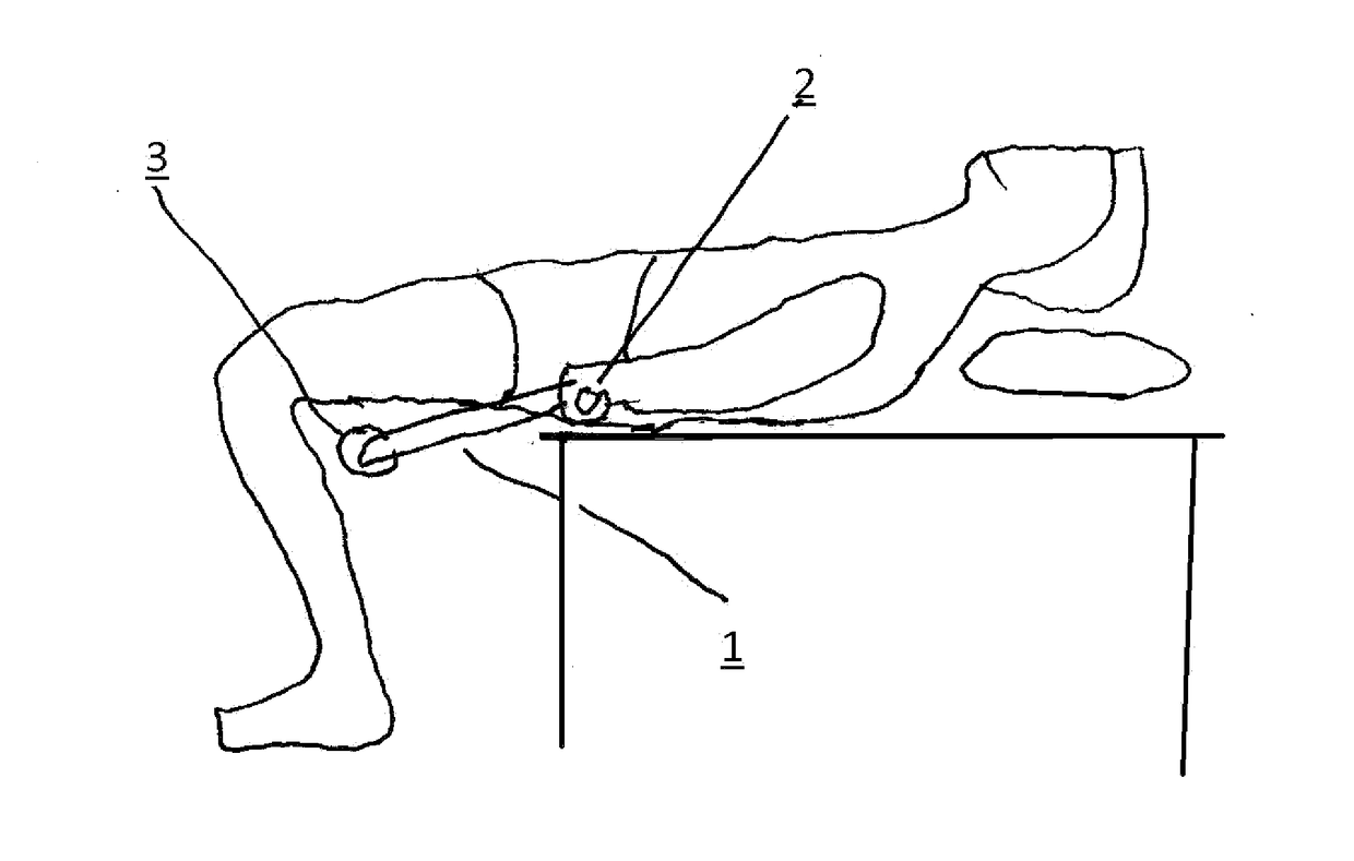
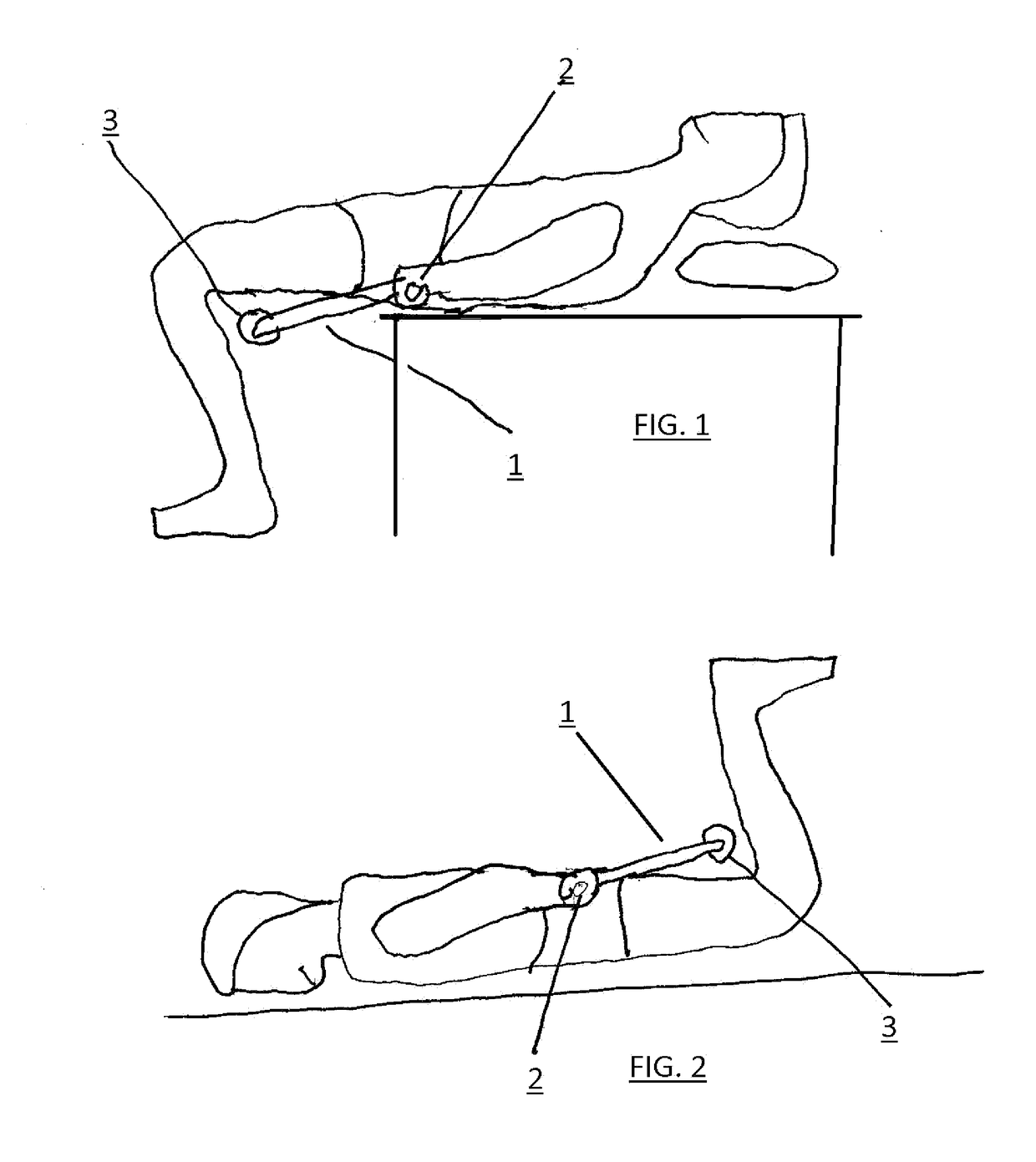
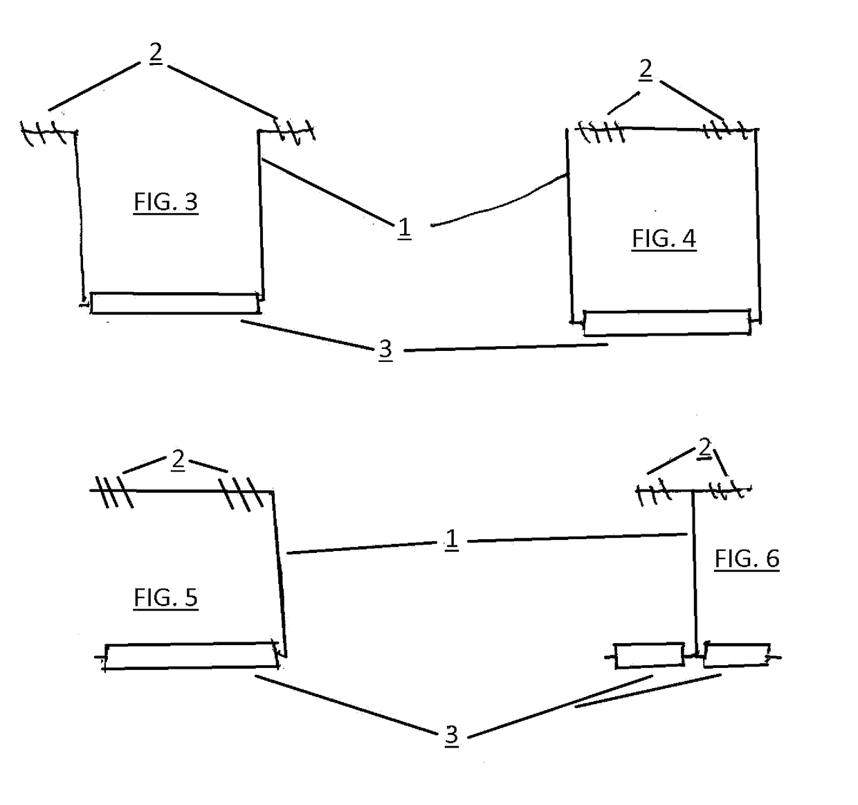
[0013]The present invention is a very simple device meant to put ones back in traction or in an extended state for the purpose of pain relief and stretching of the back muscles. This done by a person lying on their back (FIG. 1) or on their stomach (FIG. 2) with their legs bent at the knees, the device is pushed with the handle portion (“2”) threw the vertical portion (“1”) which is attached to the horizontal bar (“3”) pushing on the back of the persons upper calves. This then pushes the legs of the person in one direction and the shoulders in the other direction stretching the person's back and opening the gaps between the vertebrae and stretching muscles relieving pain. The bars and handles can have many cross sections such as but not limited to tubular, solid round, square ect., as long as it is strong enough to keep its embodied shape during use. The handles (“2”) may or may not have a comfortable grip applied as indicated or come with a ball or grip that extends from the end of...


PUM


Abstract

A device that is used to extend the spine and put it in traction, that is portable and user friendly. The device in its preferred embodiment is grasped by the handles on either side and then is pushed toward the lower leg and against the upper calves via vertical intermediary bar pushing the legs with a horizontal bar in one direction and the shoulders in the other. The described process stretching the spine and putting the back in traction for the purposes of pain relief and stretching of the back muscles.The invention or device is meant to be an inexpensive alternative to other devices, as well as, easier to use. The lower cost of the device due to it its unique and simple design being an incentive purchase the device, thus, bringing pain relief to more people.The method for use of the device can be as the preferred embodiment or it can be imagined in several other designs, but still retaining the method employed in the preferred embodiment, this application is meant to cover all such eventualities and shapes.The force placed on the device and therefore on the spine or back is controlled by the user as is the ability to stop quite quickly if pain where to arise, giving the user complete and instant control. Other embodiments may include the ability to take the device apart for travel or to lengthen or shorten the device to accommodate different sizes of people.The method of use being unique, in that it requires the user to lay on their back or stomach with the thigh portion of their leg flat and in line with the torso of the person and the legs bent at the knees, this method of use being a more natural and safe position.The device in its preferred and other embodiments being easier and more effective for grossly overweight people whereas the weight of the person or encumbrance of the extended abdomen making other devices less effective and harder to use than the present invention. The present device is not reliant on the weight of the person to achieve traction in the spine or back.

Description

[0001]This is a provisional application under 35 USC section 111 (b)BACKGROUND[0002]The present invention relates to a simple device consisting of bars fashioned so that there is a horizontal bar that is padded and at least one vertical bar with grip handles mounted on the opposite end of the vertical bar in a fashion that a person can grab them easily. The horizontal bar is then placed behind the upper calves area of the user in laying down in a flat position, with the torso and the thigh area of the legs in line, with their legs bent at the knee. The person would then grip the grip handles and push on the backs of the calves, thus pushing the legs in one direction and the shoulders in the other direction lengthening the spine and putting it in traction to relieve back pain and stretch back muscles. This device was conceived out of necessity to alleviate the inventors own back pain. To my knowledge, this is the simplest and least expensive unique unit that is designed for back trac...

Claims


Application Information

Patent Timeline
IPC IPC(8): A63B23/02A63B21/00
CPCA63B23/0238A63B21/00185A63B21/4035A63B2023/006A63B2210/50
Inventor CULLISON, ROBERT FLOYD
Owner CULLISON ROBERT F
Learn More