
Controller for a three-phase brushless D.C. motor

a three-phase brushless d.c. motor and controller technology, applied in the direction of dynamo-electric machines, single motor speed/torque control, synchronous motor starters, etc., can solve the problem that the controller of this type tends to produce undesired torque variations of the motor, and achieves low cost and simple manner

Active Publication Date: 2016-08-02
JOHNSON ELECTRIC SA
View PDF7 Cites 0 Cited by
  • Summary
  • Abstract
  • Description
  • Claims
  • Application Information

AI Technical Summary

Benefits of technology

[0006]Hence there is a desire for an improved controller of this type, which can serve to limit the variations of the torque supplied by the motor.
[0007]It is preferred that the improved controller can be made by using relatively simple and inexpensive devices.
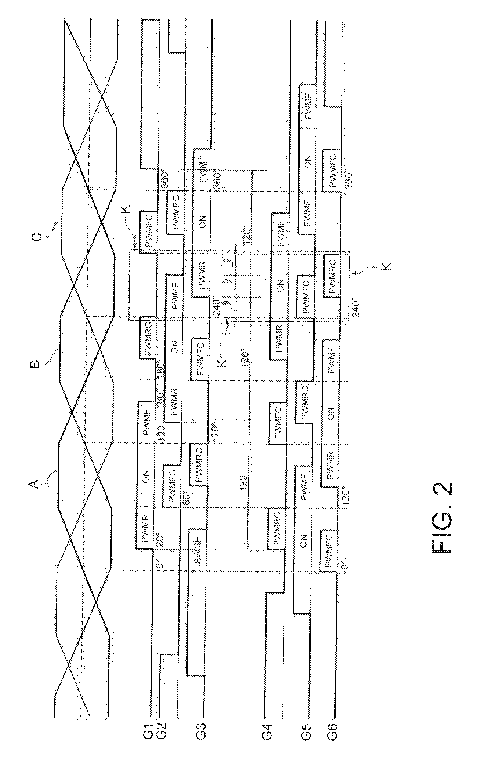
[0011]Preferably, the electronic control unit is arranged to drive, in steady state, the switches with drive signals whose active or conducting portion is variable as a function of the speed of the motor and / or the current drawn thereby, in such a way that the torque ripple is reduced.
[0013]Preferably, the width or duration of the pulses of the initial interval and the final interval varies in accordance with a predetermined time profile, in such a way that the torque ripple is reduced.
[0018]Therefore the controller according to the invention can be used to provide a pseudo-sinusoidal current system in a relatively simple manner and at low cost.

Problems solved by technology

However, controllers of this type tend to produce undesired variations in torque supplied by the motor.

Method used


Image

  • Controller for a three-phase brushless D.C. motor
  • Controller for a three-phase brushless D.C. motor
  • Controller for a three-phase brushless D.C. motor

Examples


Embodiment Construction

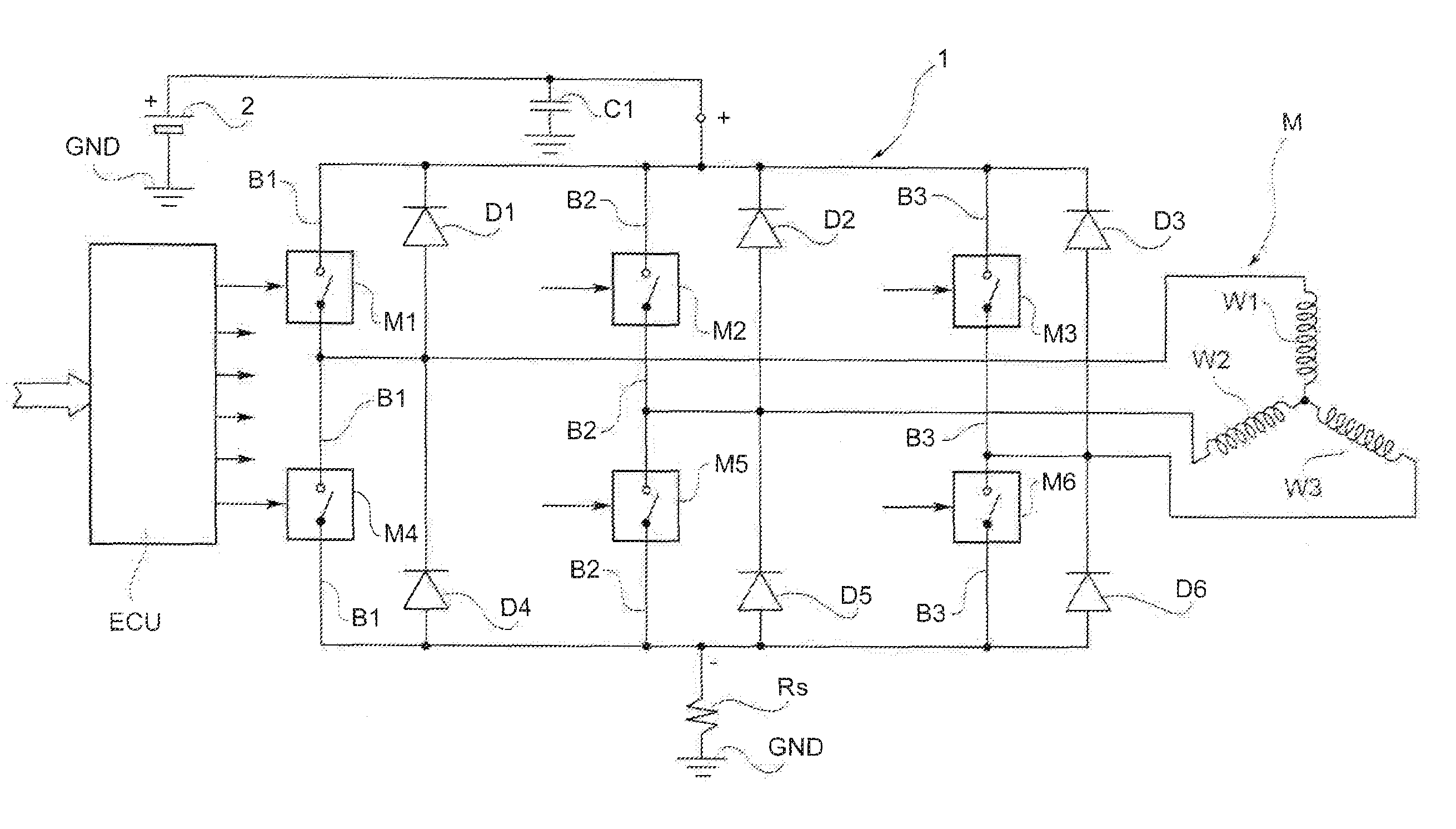
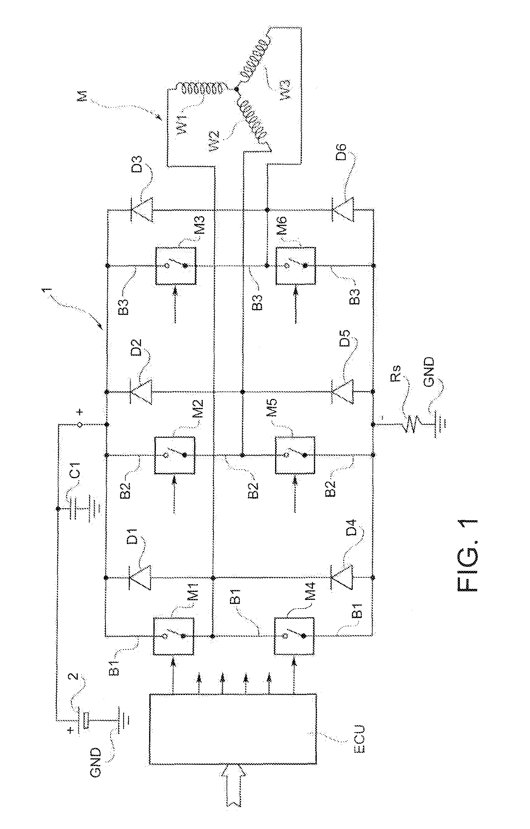
[0024]FIG. 1 illustrates the general structure of a controller for a three-phase brushless D.C. motor, according to the present invention. This controller comprises a full bridge circuit I, including three circuit branches indicated by B1, B2 and B3, These circuit branches are connected between the two poles of a D.C. voltage supply source 2 which, in the illustrated exemplary embodiment, has its negative pole connected to an earth conductor GND.

[0025]The branches B1, B2 and B3 of the bridge circuit 1 comprise respective upper electronic switches M1, M2 and M3, and respective lower electronic switches M4, M5 and M6, interconnected in order and connected to the positive pole and the negative pole, respectively, of the source 2.

[0026]These electronic switches are preferably transistors of the MOSFET type.

[0027]The bridge circuit 1 is connected to a brushless motor M, having three phases or windings W1, W2 and W3, which in the illustrated embodiment are interconnected in a star configu...


PUM


Abstract

Controller for a three-phase brushless D.C. motor has a full bridge circuit and an electronic control unit (ECU). The full bridge circuit has three branches each with switches connected to the motor windings. The switches are driven by signals from the ECU. The drive signals are arranged in two sets of three signals. The two sets are offset by 180 electrical degrees. The drive signals of each set are offset by 120 electrical degrees and each have an active portion, alternating with an inactive portion. The active portion includes an initial interval of pulsed activation, an intermediate interval of continuous activation, and a final interval of pulsed activation. The active portion of the drive signals is greater than 120 electrical degrees, with each initial interval of pulsed activation of a switch overlapping the final interval of the previously activated switch.

Description

CROSS REFERENCE TO RELATED APPLICATIONS[0001]This non-provisional patent application claims priority under 35 U.S.C. §119(a) from Patent Application No. TO2012A000311 filed in Italy on Apr. 10, 2012, the entire contents of which are incorporated herein by reference.FIELD OF THE INVENTION[0002]This invention relates to a controller for an electric motor and in particular, to a controller for a three-phase brushless D.C. motor.BACKGROUND OF THE INVENTION[0003]More specifically, the invention proposes a controller for a three-phase brushless motor, comprising: a full bridge circuit, including three circuit branches connected between the two poles of a D.C. voltage supply source, each branch comprising an upper electronic switch and a lower electronic switch, connected with each other and connected to the positive pole and the negative pole, respectively, of said source, each of the windings or phases of the motor being connected to an intermediate point between the two switches of a co...

Claims


Application Information

Patent Timeline
Patent Type & Authority Patents(United States)
IPC IPC(8): H02P6/10H02P6/08H02P6/14H02P6/00
CPCH02P6/10H02P6/14H02P6/00H02P6/08H02P6/32
Inventor MARCHITTO, LUCIANOPERNA, GIANFRANCOPANGELLA, PIERFRANCOGOBBETTI, GIANLUCA
Owner JOHNSON ELECTRIC SA
Learn More