Pedestal of molding extraction machine

a molding extraction machine and pedestal technology, applied in the field of pedestal, can solve the problems of claw 30/b>, move left and right or up and down, and achieve the effect of stable carrying

Inactive Publication Date: 2018-09-06
FANUC LTD
View PDF1 Cites 2 Cited by
  • Summary
  • Abstract
  • Description
  • Claims
  • Application Information

AI Technical Summary

Benefits of technology

[0014]According to an aspect of the invention, there is provided a pedestal of a molding extraction machine for aligning and arranging a molded product from an injection molding machine, including: a first surface; and a second surface facing the first surface, in which the first surface is provided with a first hole forming member forming a first hole and the second surface is provided with a second hole forming member forming a second hole, and in which the first hole and the second hole are provided with a through-hole forming member forming at least one through-hole through which a carrying member carrying the pedestal is insertable. In the pedestal of the embodiment of the invention, since the pedestal itself is provided with at least one through-hole through which the carrying member can be inserted, there is no need to particularly attach the transportation member for inserting the carrying member thereinto. Further, since the through-hole into which the carrying member is inserted is provided, it is possible to stably carry the molding extraction machine using the carrying member.
[0016]In the pedestal of the molding extraction machine, since the through-hole is provided in the vicinity of the position of the center of gravity of the entire apparatus in the height direction, it is possible to more stably carry the molding extraction machine using the carrying member.
[0018]In the pedestal of the molding extraction machine, since the through-hole is provided at a plurality of different positions of the pedestal in the height direction, it is possible to more stably carry the molding extraction machine by inserting the carrying member into the through-hole best suitable for the weight and the position of the center of gravity even when the weight changes in response to the type of molding extraction machine to be mounted.
[0020]In the pedestal of the molding extraction machine, since another through-hole is formed in a direction orthogonal to the initial through-hole, it is possible to cope with different carrying members and to cope with a case where the carrying member cannot be inserted into the through-hole from one direction depending on the pedestal installation position by the use of the initial through-hole and another through-hole.
[0023]According to the invention, it is possible to provide a pedestal of a molding extraction machine which can be stably carried without a particular transportation member attached thereto.

Problems solved by technology

As a result, there is concern that the claw 30 of the forklift inserted into the insertion position may move left and right or up and down when the molded product aligning apparatus moves.

Method used


Image

  • Pedestal of molding extraction machine
  • Pedestal of molding extraction machine
  • Pedestal of molding extraction machine

Examples


first embodiment

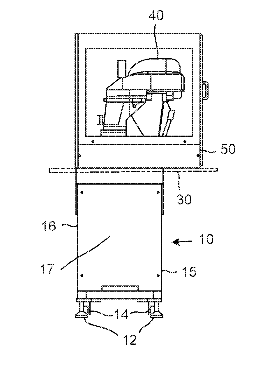
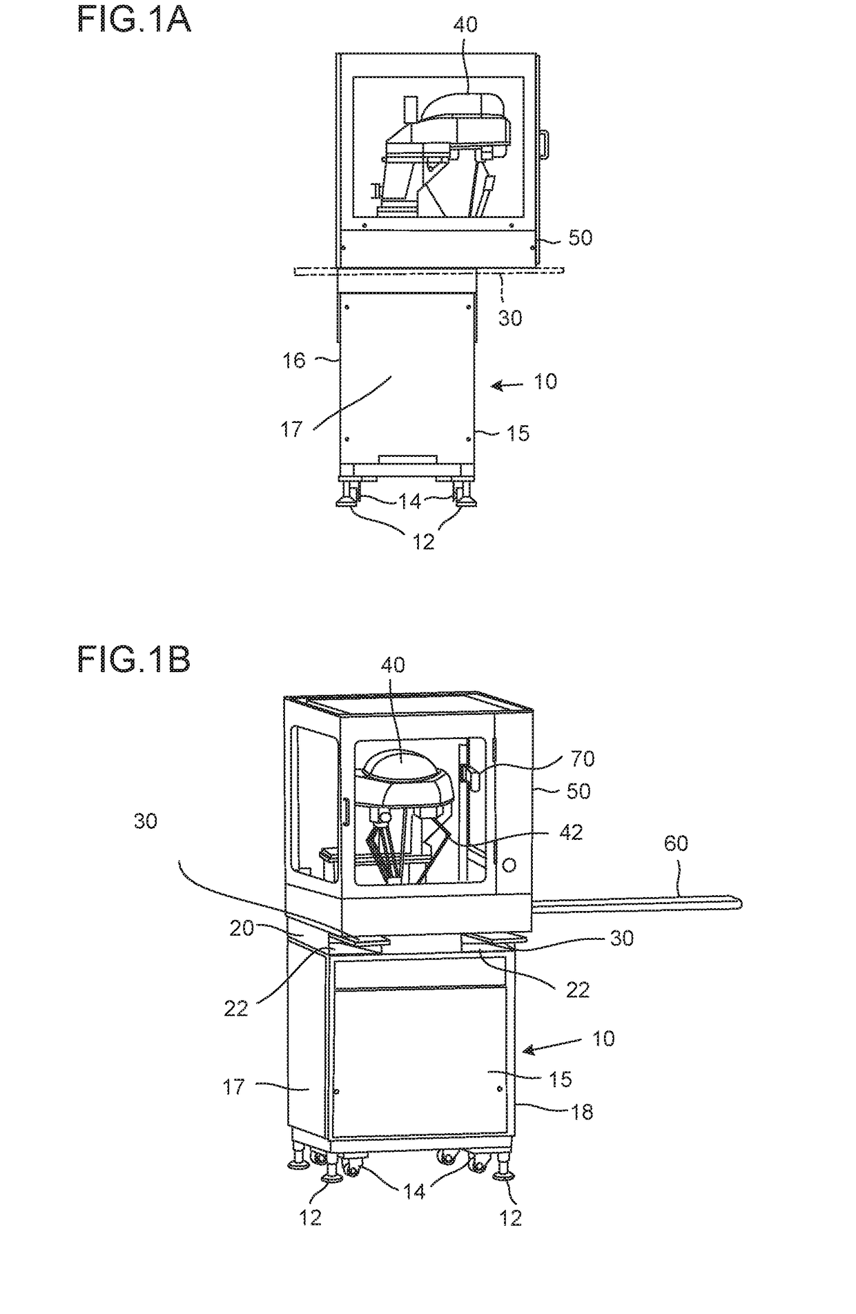
[0034]FIGS. 1A and 1B are diagrams illustrating a molded product aligning apparatus of the embodiment, where FIG. 1A illustrates a side view of the apparatus and FIG. 1B illustrates a perspective view of the apparatus. Components similar to those of the related art illustrated in FIGS. 4 and 5 will be denoted by the same reference numerals and a description thereof will be omitted.

[0035]In the embodiment, a pedestal 10 has a substantially rectangular parallelepiped shape and is formed to surround a front surface portion 15, a rear surface portion 16, a left side surface portion 17, a right side surface portion 18, and upper and lower surface portions (not illustrated). An upper portion of the pedestal 10 is provided with a carrying member insertion portion 20 and a hole is provided at two left and right positions of the front surface portion 15 and the rear surface portion 16 of the carrying member insertion portion 20 in the front view. The holes provided in the front surface porti...

second embodiment

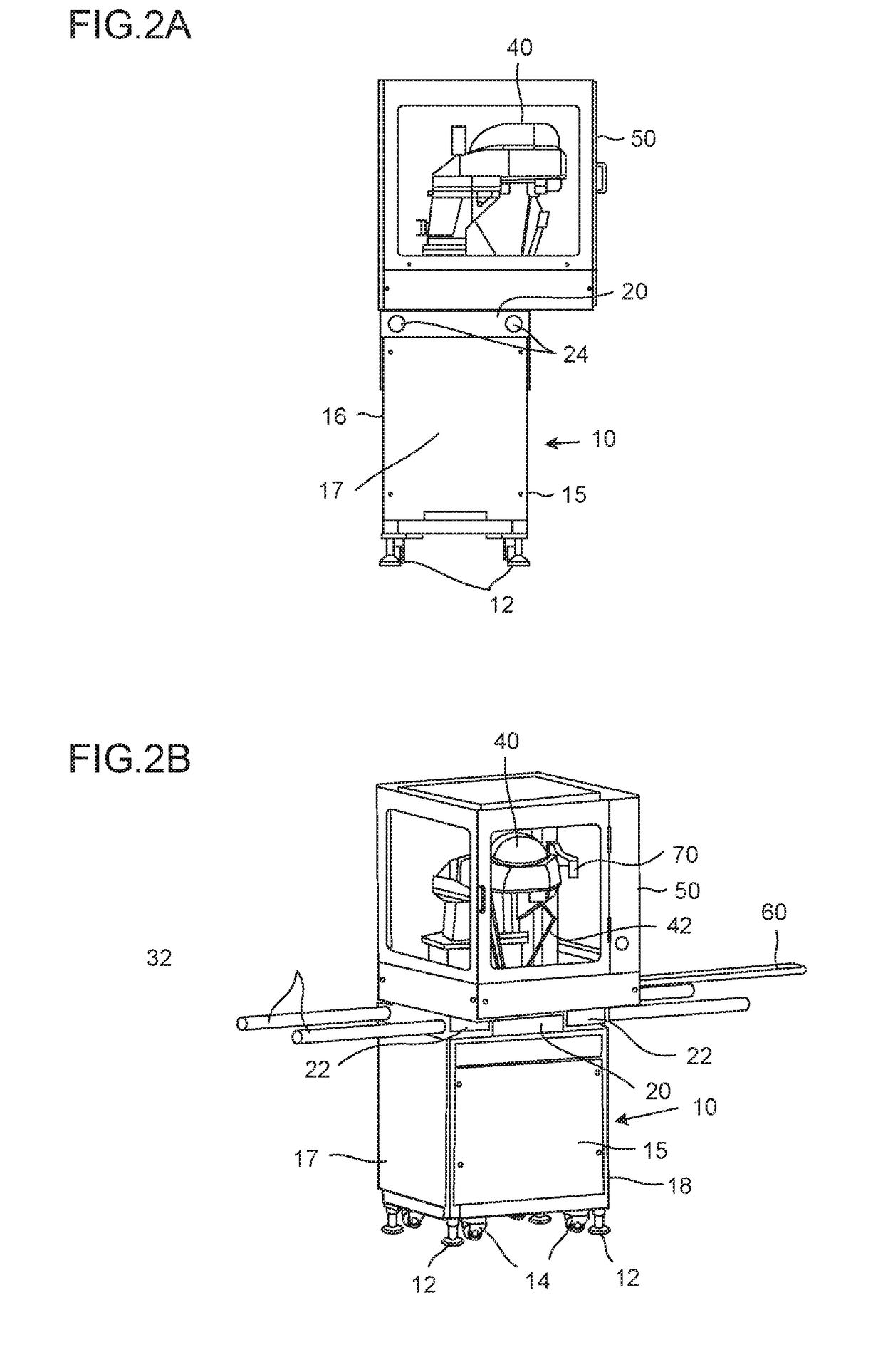
[0041]FIGS. 2A and 2B are diagrams illustrating a molded product aligning apparatus of the embodiment, where FIG. 2A is a side view of the apparatus and FIG. 2B is a perspective view of the apparatus. Also in the embodiment, the same reference numerals will be given to the same components as those of the related arts illustrated in FIGS. 4 and 5 and a description thereof will be omitted.

[0042]In the embodiment, a pedestal 10 has a substantially rectangular parallelepiped shape and is formed to surround a front surface portion 15, a rear surface portion 16, a left side surface portion 17, a right side surface portion 18, and upper and lower surface portions (not illustrated). An upper portion of the pedestal 10 is provided with a carrying member insertion portion 20 and a hole is provided at two left and right positions of the left side surface portion 17 and the right side surface portion 18 of the carrying member insertion portion 20 in the side view. The holes provided in the left...

modified example

[0049]An example illustrated in FIGS. 3A and 3B is a modified example of the example illustrated in FIGS. 1A and 1B and a through-hole 22 is provided at a plurality of different positions in the height direction. Since the molding extraction machine 40 to be mounted on the pedestal 10 is generally known, it is enough to use the through-hole 22 provided at a determined position. However, in a case where the molding extraction machine 40 having a different size or weight is mounted on the pedestal, it is possible to more stably carry the molding extraction machine when the through-hole 22 is provided at a plurality of different positions in the height direction similarly to the example illustrated in FIGS. 3A and 3B and the molding extraction machine is carried by the carrying member using the through-hole 22 best suitable for the molding extraction machine 40 mounted thereon.

[0050]A modified example of the example illustrated in FIGS. 1A and 1B has been described, but the through-hol...


PUM

PropertyMeasurementUnit
gravityaaaaaaaaaa
heightaaaaaaaaaa
mold clamping forceaaaaaaaaaa

Abstract

Provided is a pedestal of a molding extraction machine which may be stably carried without a particular transportation member attached thereto. In the pedestal of the molding extraction machine sorting a molded product from an injection molding machine, at least one through-hole into which a carrying member for carrying the pedestal may be inserted is provided and the carrying member such as a forklift or a hanger rod is inserted into the through-hole so that the molding extraction machine may be carried. Accordingly, there is no need to particularly attach a transportation member and the molding extraction machine may be stably carried by the carrying member.

Description

BACKGROUND OF THE INVENTION1. Field of the Invention[0001]The present invention relates to a pedestal and more particularly to a pedestal of a molding extraction machine for ejecting a molded product of an injection molding machine.2. Description of the Related Art[0002]An injection molding machine mainly includes a mold clamping device which opens and closes a mold to generate a mold clamping force and an injection device which melts resin and injects the melted resin into the mold, and the mold clamping device and the injection device are disposed to face each other. The resin which is injected into the mold is solidified to become a molded product and is ejected by an ejector.[0003]The molded product which is ejected from the injection molding machine is carried by a conveyor. Then, the molded product is gripped by the molding extraction machine and is disposed in a molded product aligning tray (not illustrated) based on information from a monitoring device. In some cases, the co...

Claims


Application Information

Patent Timeline
Patent Type & Authority Applications(United States)
IPC IPC(8): B29C45/42
CPCB29C45/42B29C2045/4241
Inventor OHSHIRO, KATSUFUMI
Owner FANUC LTD
Why Eureka
Try Eureka