Glass film laminate, method of producing the same, and method of producing glass film
Active Publication Date: 2012-04-05
NIPPON ELECTRIC GLASS CO LTD
View PDF11 Cites 36 Cited by
- Summary
- Abstract
- Description
- Claims
- Application Information
AI Technical Summary
Benefits of technology
[0025]According to the present invention, the adhering portion between the contacting surface of the glass film and the contacting surface of the supporting member comprises the region with a relatively strong adhesive force and the region with a relatively weak adhesive force, and hence treatment associated with production can be stably carried out in the state in which the glass film is firmly laminated on the supporting member due to the region with a relatively strong adhesive force. In addition, the adhering portion comprises the region with a relatively weak adhesive force, and hence it is possible to easily peel the glass film from the region with a relatively weak adhesive force after the treatment associated with production. Thus, it is possible to prevent an improper peeling and removal of a glass film during treatment associated with production in a case of an adhesive force of an adhering portion being overall too week, while preventing the breakage of a glass film at the time of peeling in a case of an adhesive force of an adhering portion being overall too strong.
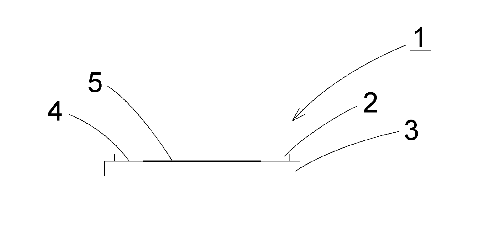
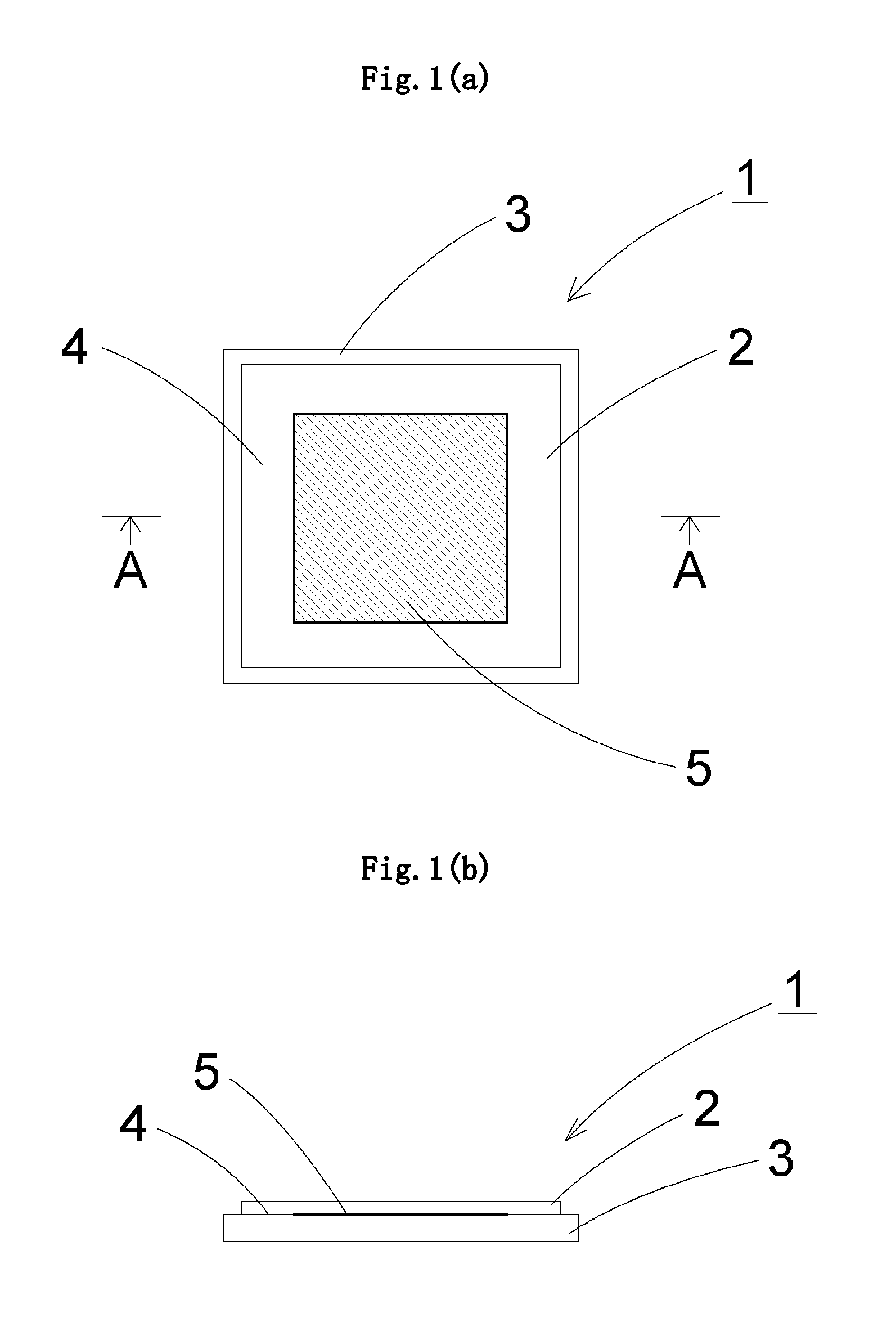
[0026]When the supporting member is formed of glass (supporting glass) and at least one of the contacting surface of the glass film and the contacting surface of the supporting glass comprises the region with a relatively large surface roughness and the region with a relatively small surface roughness, the glass film and the supporting glass becomes adhered weakly in the region with a relatively large surface roughness (hereinafter, referred to as rough surface), and the glass film and the supporting glass becomes adhered strongly in the region with a relatively small surface roughness (hereinafter, referred to as smooth surface). It is considered that, when smooth surfaces are brought into contact with each other, the distance between both the surfaces becomes small to such an extent as hydroxyl groups existing on both the surfaces can form hydrogen adhering. Thus, it is considered that both the surfaces are adhered with good adhesiveness and the contacting surface of the glass film and the contacting surface of the supporting glass can be adhered strongly and stably even if no adhesive is used. As a result, treatment associated with production can be stably carried out in the state in which the glass film is firmly laminated on the supporting glass, and the glass film can be easily peeled from the rough surface after the treatment associated with production as well. Besides, as no adhesive is used, the glass film has no remaining adhesive after the glass film is peeled from the supporting glass.
[0027]The supporting glass can be reused. When the contacting surface of the supporting glass comprises the region with a relatively large surface roughness and the region with a relatively small surface roughness, carrying out roughening treatment once on a partial region of the contacting surface of the supporting glass, for example, enables to reuse the supporting glass without any additional roughening treatment, leading to simplification of the production process. On the other hand, roughening treatment on the glass film may not be preferred in some cases even if the roughening treatment is carried out on its back surface side because the glass film is used as a glass substrate for devices.
[0028]When the region with a relatively small surface roughness has a surface roughness Ra of 2.0 nm or less, the glass film and the supporting glass can be adhered more firmly.
[0029]When the difference in surface roughness Ra between the region with a relatively large surface roughness and the region with a relatively small surface roughness is 0.1 nm or more, the glass film and the supporting glass can be adhered properly, good positioning can be made in treatment associated with production, and the glass film can be easily peeled from the supporting glass after the treatment associated with production. Consequently, it becomes possible to strike a balance between adhesive property and peeling property.
[0030]When the contacting surface comprises the region with a relatively large surface roughness at an outer peripheral portion thereof and the region with a relatively small surface roughness at an inner portion surrounded by the outer peripheral, the glass film and the supporting glass can be firmly adhered with a small adhesive area along the outer peripheral portion of the contacting surface. Besides, even if treatment associated with production includes a process in which a solvent is used, it is possible to prevent the solvent from entering a gap between the glass film and the supporting glass.
Problems solved by technology
However, glass used for a substrate is weak in tensile stress unlike a resin film, and hence is low in flexibility.
Thus, application of a tensile stress on a surface of a glass substrate by bending the glass substrate leads to the breakage of the glass substrate.
However, when a glass film is used as a glass substrate for those electronic devices, the glass film breaks easily due to even a slight stress change, because glass is a brittle material.
Thus, there is a problem in that the handling of the glass film is very difficult, when the above-mentioned various treatments associated with electronic device production are carried out.
In addition, there is another problem in that a glass film having a thickness of 200 μm or less is rich in flexibility, and hence the positioning of the glass film is difficult when the treatments associated with production are carried out, and displacement or the like in patterning may occur.
In addition, such a problem in that the laminate is displaced when positioning and patterning during treatment associated with production is unlikely to be occurred, because the supporting member has a high rigidity.
Method used
View moreImage
Smart ImageViewing Examples
Examples
example 1
[0075]Hereinafter, the glass film laminate of the present invention is described in detail based on examples, but the present invention is not limited to those examples.
Login to View More PUM
| Property | Measurement | Unit |
|---|---|---|
| Surface roughness | aaaaa | aaaaa |
| Surface roughness | aaaaa | aaaaa |
| Force | aaaaa | aaaaa |
Abstract
A glass film laminate comprises a glass film (2) and a supporting glass (3) laminated to each other. At least one of the contacting surface of the glass film (2) and the contacting surface of the supporting glass (3) comprises a region with a relatively large surface roughness and a region with a relatively small surface roughness.
Description
TECHNICAL FIELD[0001]The present invention relates to a glass film laminate in which a glass film to be used for a glass substrate for an electronic device, such as a flat panel display typified by a liquid crystal display or an OLED display, a solar cell, a lithium ion battery, a digital signage, a touch panel, and an electronic paper, or a glass film to be used for a cover glass for an OLED lighting device, a package for a medicinal product, and the like is supported with a supporting glass, and to a glass film.BACKGROUND ART[0002]In recent years, from the viewpoint of space saving, there have been widely used flat panel displays such as a liquid crystal display, a plasma display, an OLED display, and a field emission display, in place of a CRT type display which is conventionally widely used. Further reduction in thickness is demanded for those flat panel displays. In particular, it is required that the OLED display be easily carried by being folded or wound and be usable not onl...
Claims
Login to View More Application Information
Patent Timeline
 IPC IPC(8): B32B38/10B32B7/02B32B17/06
CPCB32B7/06C03C17/002Y10T428/24612C03C27/00Y10T428/24926B32B17/06
Inventor TOMAMOTO, MASAHIROFUJII, TAKAHIDETAKIMOTO, HIROSHI
Owner NIPPON ELECTRIC GLASS CO LTD
Features
- R&D
- Intellectual Property
- Life Sciences
- Materials
- Tech Scout
- Unparalleled Data Quality
- Higher Quality Content
- 60% Fewer Hallucinations
Learn More Browse by: Latest US Patents, China's latest patents, Technical Efficacy Thesaurus, Application Domain, Technology Topic, Popular Technical Reports.
© 2025 PatSnap. All rights reserved.Legal|Privacy policy|Modern Slavery Act Transparency Statement|Sitemap|About US| Contact US: help@patsnap.com


