
Metallic foil manufacturing method and cathode for manufacturing metallic foil

Active Publication Date: 2021-01-26
HITACHI METALS LTD
View PDF22 Cites 0 Cited by
  • Summary
  • Abstract
  • Description
  • Claims
  • Application Information

AI Technical Summary

Benefits of technology

The invention makes it easy to peel off a metal film from a surface and reduces the roughness of the surface when the metal film is peeled off. This technique is useful for making metallic foils, such as aluminum foil, that are suitable for use as the main body of a positive electrode current collector.

Problems solved by technology

This is because the standard electrode potential of aluminum is lower than hydrogen and it is difficult to apply electrolysis that is suitable for thinning, but recently research and development for manufacturing an aluminum foil by electrolysis is proceeding.
It is confirmed that even the electrodeposition surface is made of a titanium material, fine recesses are generated due to corrosion or oxidation dining continuous use, and peelability of the electrodeposited copper (copper film) is deteriorated, which adversely affects the quality of the copper foil (Patent Literatures 2 to 6).

Method used


Image

  • Metallic foil manufacturing method and cathode for manufacturing metallic foil
  • Metallic foil manufacturing method and cathode for manufacturing metallic foil
  • Metallic foil manufacturing method and cathode for manufacturing metallic foil

Examples


example

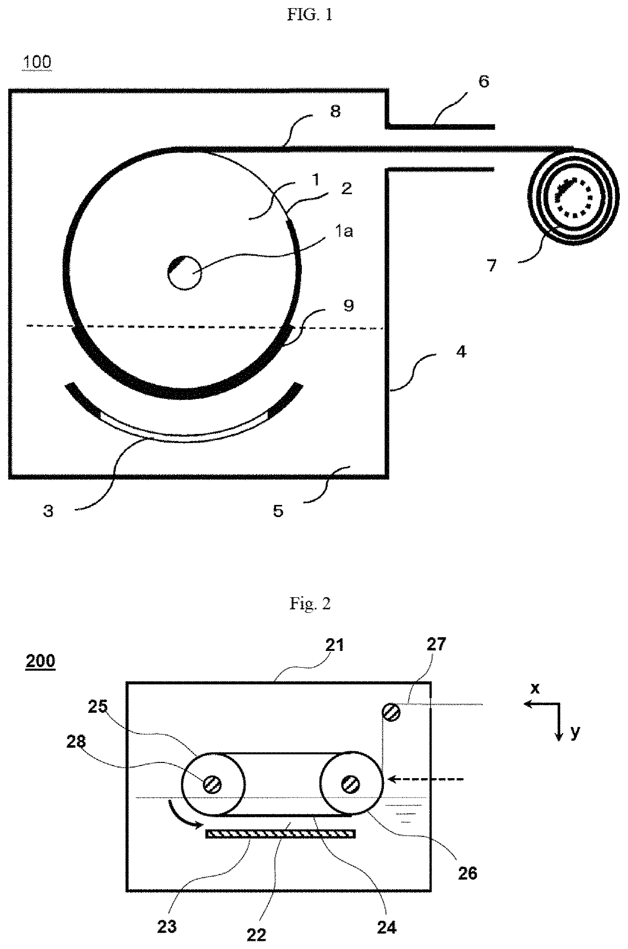
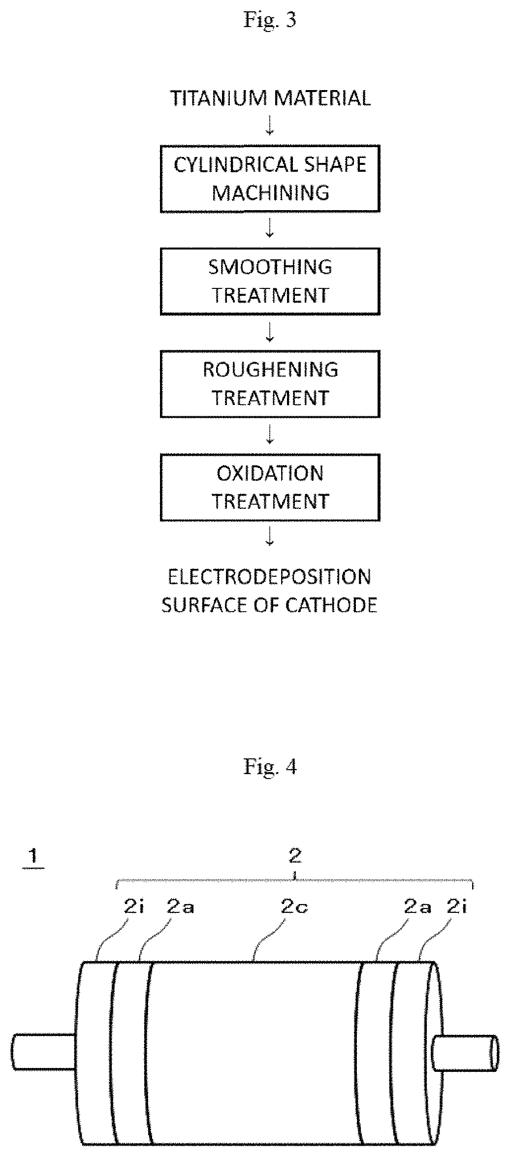
[0076]The invention will be described in detail by way of examples which are considered to be preferable and comparative examples. For convenience, the descriptions shown in FIGS. 1 to 4 are used for explanation. The invention is not intended to be limited to the following description.

[0077]In the example of the invention and comparative examples, an aluminum toil (metallic foil) having a thickness of 12 μm and a width of 600 mm was manufactured by electrolysis using a cathode drum 1 provided with a copper lead member 8 formed by electrolysis on an outer periphery 2. The outer periphery 2 of the cathode drum 1 was made of titanium and was divided into five regions (center portion 2c, two adjacent portions 2a, and two insulating portions 2i) in a body length direction (width direction). The lead member 8 was a copper foil (electrolytic copper foil) formed by partway peeling off a copper film formed by electrolysis from the outer periphery 2 of the cathode drum 1. Therefore, when the ...


PUM

PropertyMeasurementUnit
Lengthaaaaaaaaaa
Lengthaaaaaaaaaa
Lengthaaaaaaaaaa

Abstract

Provided are a metallic foil manufacturing method in which a metallic film electrodeposited by electrolysis on the surface of an electrodeposition surface of a cathode is peeled off to form a metallic foil, and the electrodeposition surface used therein is obtained by subjecting a roughened surface, which results from roughening a smoothed surface made of titanium or titanium alloy using a blast treatment, etc., to an oxidation treatment selected from thermal oxidation, anodic oxidation (preferably anodic oxidation carried out while moving the anodic oxidation solution), or a combination treatment of thermal oxidation and anodic oxidation so that the electrodeposition surface has an oxidation layer with a thickness of 30 to 250 nm on the uppermost layer and has a surface roughness RZJIS of 4 to 10 μm.

Description

TECHNICAL FIELD[0001]The present invention relates to a metallic foil manufacturing method and a cathode for manufacturing a metallic foil. For example, the invention relates to a metallic foil manufacturing method in which a metallic film of aluminum, copper or the like that is electrodeposited by electrolysis on a surface of an electrodeposition surface of a cathode for manufacturing a metallic foil is peeled off to form a metallic foil, and the cathode for manufacturing a metallic foil which is preferable when being used therein.BACKGROUND ART[0002]In recent years, electric storage devices typified by lithium-ion secondary batteries, super capacitors (such as electric double layer capacitors, redox capacitors, lithium-ion capacitors, etc.) or the like that can be repeatedly charged and discharged, and have high capacity and high energy density is increasingly used, and research and development on the increase in capacity and energy density have progressed prosperously and the dem...

Claims


Application Information

Patent Timeline
IPC IPC(8): C25D1/20C25D1/04C23C8/02C23C8/10C25D11/26
CPCC25D1/20C23C8/02C23C8/10C25D1/04C25D11/26C25D1/00C23C8/40C23C8/42H01M4/662H01M4/667Y02E60/10
Inventor MATSUDA, JUNICHIOKAMOTO, ATSUSHI
Owner HITACHI METALS LTD
Learn More