

Composite copper foil and method of fabricating the same
- Summary
- Abstract
- Description
- Claims
- Application Information
AI Technical Summary
Benefits of technology
Problems solved by technology
Method used
Image

Examples
exemplary embodiment 1
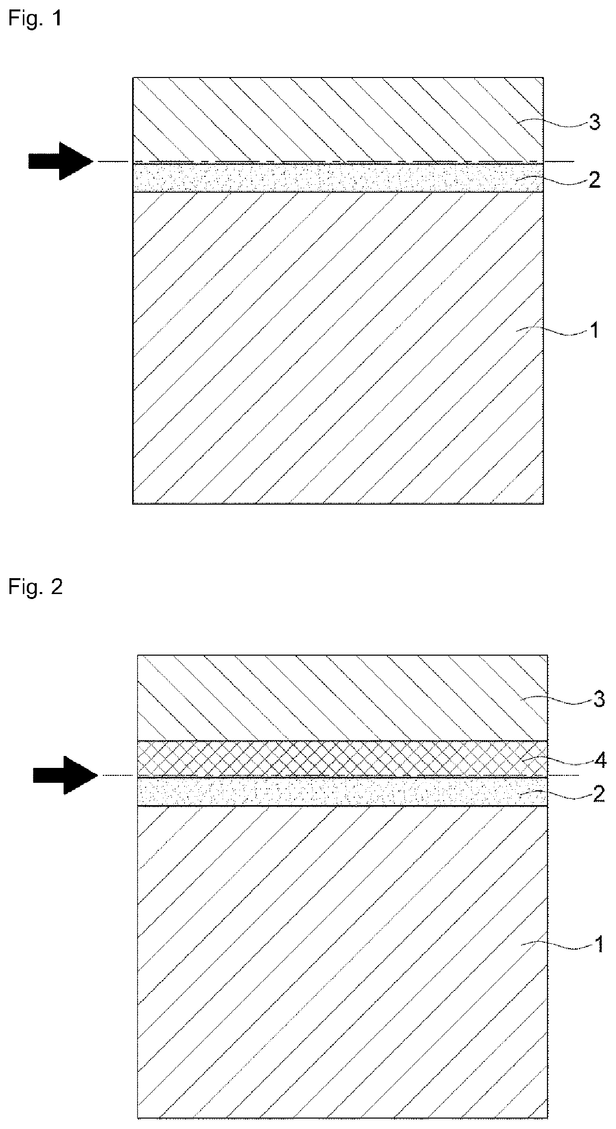
[0082]First, copper was acid cleaned, and then a carrier layer was formed using a copper foil. Electroplating was performed on the carrier layer by using an electrolyte that includes, for example, nickel (Ni), molybdenum (Mo), or / and tungsten (W), and thus an alloy release layer was formed. The electrolyte was prepared by adding nickel sulfate hydrate of 50 g, molybdenum sodium dihydrate of 20 g, and tungsten dihydrate of 5 g to water of 1000 ml. A temperature of the electrolyte was adjusted to 22° C., and a current density thereof was adjusted to 1 A / dm2 to 2 A / dm2. A pH was adjusted to 4 during electrolysis.
[0083]When the release layer which includes metal was exposed to air for 40 seconds by electroplating, its surface was oxidized to form an oxide.
[0084]Then, Ni—P was plated on the release layer 2, and thus a laser drilling layer was formed. In such a case, an electrolyte was prepared by adding nickel of 5 g and NaH2PO2 of 6 g to water of 1000 ml, and a pH was adjusted to 3.5 du...
experimental example 1
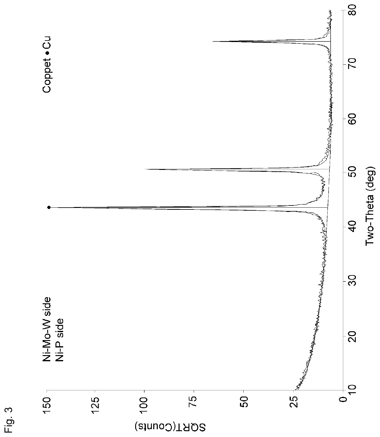
[0087]1. GIXRD Measurement
[0088]The composite copper foil according to Exemplary Embodiment 1 was thinly peeled, thus exposing the release layer (Ni—Mo—W layer) and the metal layer (Ni—P layer). The two surfaces were directly placed on a diffractometer, and GIXRD data was measured and collected, and the results are shown in FIG. 3. The incidence angle was fixed at 0.7 degrees.
[0089]FIG. 3 shows a comparison of the GIXRD data of the two samples and the best matching data between the background extracted raw data of the two samples and the ICDD / ICSD diffraction database. Weak peaks in the data are plotted on a square root intensity scale for emphasis and the reference pattern for copper is displayed. No diffraction peaks other than those corresponding to the copper foil were observed. The raised bases of the two most intense copper peaks may be due to broad peaks belonging to amorphous Ni—Mo—W and Ni—P layers.
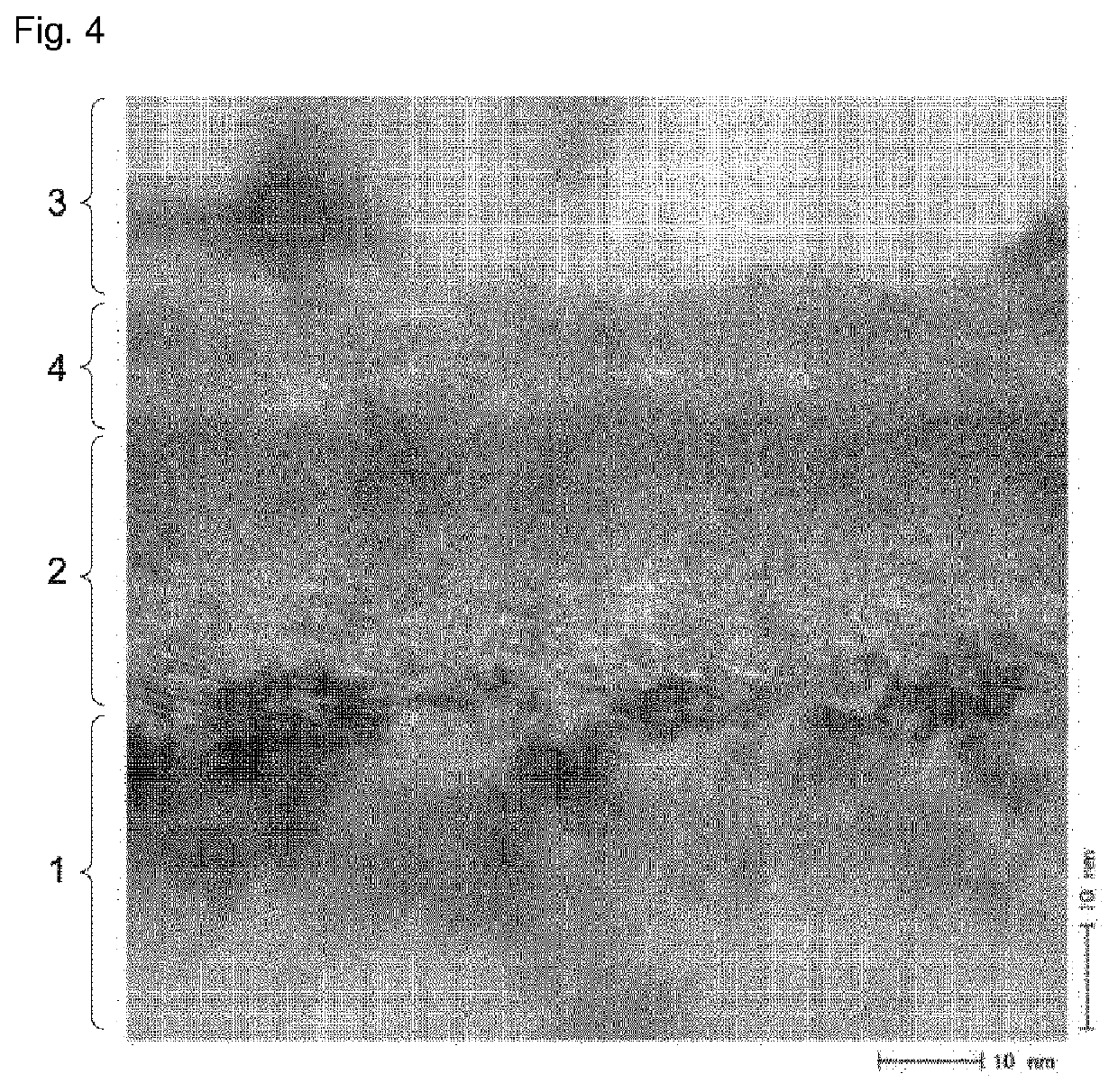
[0090]2. TEM Measurement
[0091]The composite copper foil according to Exempla...
experimental example 2
[0097]Respective ratios (atomic %) of Ni in the oxidation state were measured at a surface and at a depth of about 7 nm of the release layer of the composite copper foil according to Exemplary Embodiment 1 by X-ray photoelectron spectroscopy (“XPS”) using an ultra-high vacuum K-alpha spectrometer (manufactured by Thermo (VG) Scientiffic) with a spot size of 400 μm at 75 W, and the results are shown in Table 1 below.
TABLE 1Ni(0)NiO(wt % with respect to the(wt % with respect to thetotal 100 wt % of nickel)total 100 wt % of nickel)Surface81.418.6About 7 nm Depth86.313.7
[0098]In addition, the profile of each element forming the release layer according to the depth of the composite copper foil according to Exemplary Embodiment 1 was measured and shown in the following Table 2, which is shown in a graph and shown in FIG. 8.
TABLE 2Length (nm)CCuMoNiO0.0024.411.1522.3210.7241.401.563.060.8541.0543.1611.883.123.090.2043.6744.488.564.680.920.0145.1045.928.066.250.000.0345.7747.456.757.810.000...
PUM
| Property | Measurement | Unit |
|---|---|---|
| Time | aaaaa | aaaaa |
| Time | aaaaa | aaaaa |
| Nanoscale particle size | aaaaa | aaaaa |
Abstract
Description
Claims
Application Information