Peeling method of cover member and manufacturing method of liquid ejecting head

Active Publication Date: 2018-06-14
SEIKO EPSON CORP
View PDF0 Cites 0 Cited by
  • Summary
  • Abstract
  • Description
  • Claims
  • Application Information

AI Technical Summary

Benefits of technology

[0022]In the aspects, the substrate can be reliably protected by the cover member, destruction of the substrate can be suppre

Problems solved by technology

However, when the cover member such as the protective film is peeled off from the substrate, stress is applied to the substrate, warpage occurs in the substrate, and there is a problem that destruction such as cracks occurs.
In addition, if a force for peeling off the cover member is weak, there is a problem that the cover member cannot be peeled off from the substrate.
In addition, if an adhesive force of the cover member to the substrate is lowered, the substrate cannot be reliably protected by the cover member

Method used


Image

  • Peeling method of cover member and manufacturing method of liquid ejecting head
  • Peeling method of cover member and manufacturing method of liquid ejecting head
  • Peeling method of cover member and manufacturing method of liquid ejecting head

Examples


Example

Embodiment 1

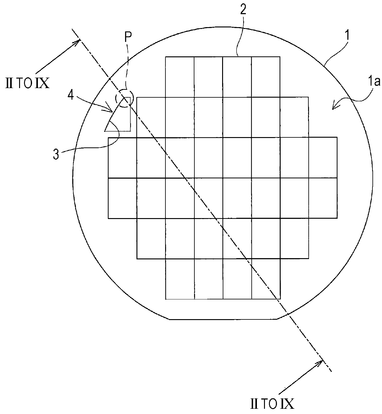
[0054]FIG. 1 is a plan view illustrating a substrate according to Embodiment 1 of the invention.

[0055]As illustrated in FIG. 1, a substrate 1 is made of a silicon wafer or the like, and has a pattern region 2 in which various patterns such as wiring, a recessed portion, and a through-hole are formed at a center portion.

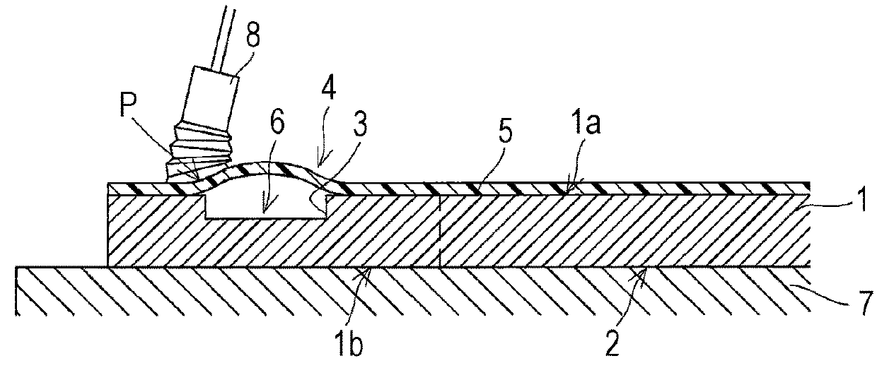
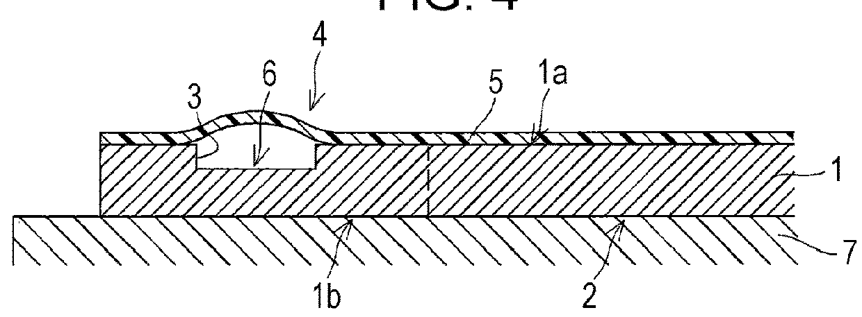
[0056]Such a substrate 1 is formed by peeling off a cover member 5 after performing processing to attach the cover member to one side surface 1a of the substrate 1 to protect the substrate 1 and form the pattern region 2, or the like on the other side surface 1b of the substrate 1.

[0057]Here, a peeling method of the cover member of the embodiment from attachment of the cover member 5 to the substrate 1 to peeling of the cover member 5 from the substrate 1 will be described with reference to FIGS. 2 to 9. Moreover, FIGS. 2 to 9 are sectional views of a main portion of line II TO IX of FIG. 1 illustrating the peeling method of the cover member.

[0058]As illus...


PUM

PropertyMeasurementUnit
Temperatureaaaaaaaaaa
Pressureaaaaaaaaaa

Abstract

Disclosed is a peeling method of a cover member including forming a recessed portion that opens one side surface of a substrate, on a region different from a region in which a pattern is formed and forming an opening region including the opening of the recessed portion; attaching the cover member so as to cover the one side surface; adjusting a pressure for increasing a pressure within a space formed by the recessed portion and the cover member by attaching the cover member to the substrate to be higher than a pressure on a side opposite to the space with the cover member interposed therebetween; and peeling off the cover member from the substrate, in a state where the pressure within the space is increased by the adjusting of the pressure.

Description

BACKGROUND1. Technical Field[0001]The present invention relates to a peeling method of a cover member for peeling off the cover member from a substrate after the cover member is attached to the substrate, and a manufacturing method of a liquid ejecting head.2. Related Art[0002]As an ink jet type recording head which is a typical example of a micro device such as a liquid ejecting head, for example, there is structure which includes a flow path forming substrate in which a pressure generating chamber communicating with a nozzle opening is formed and a pressure generating unit such as a piezoelectric actuator is formed on one side surface thereof; and a protective substrate joined to one side surface of the flow path forming substrate.[0003]In manufacturing such an ink jet type recording head, when the flow path forming substrate is processed after bonding the flow path forming substrate and the protective substrate, a protective film is attached in order to protect the protective sub...

Claims


Application Information

Patent Timeline
IPC IPC(8): B41J2/16B32B37/02B32B43/00B32B9/04B32B27/42
CPCB41J2/1607B32B37/02B32B43/006B32B9/045B32B27/42B41J2/1626B32B2386/00B32B9/04B41J2/161B41J2/1623B41J2/1628B41J2/1629B41J2/1631B41J2/1632B41J2/1642B41J2/1646B32B38/10B32B2307/546B32B3/266B32B3/30B32B27/286B32B7/12B32B7/08B32B2307/202B32B27/28B32B7/06B32B9/041B32B9/043B32B2457/14B81C1/00047B81C1/00055B81C2203/0136B81C2201/053
Inventor HOTTA, TATSURO
Owner SEIKO EPSON CORP
Why Eureka
Try Eureka