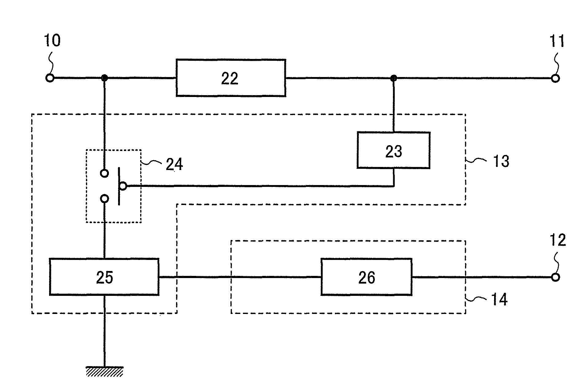
Wireless communication device
a communication device and wireless technology, applied in the field of semiconductor devices, can solve the problems of wasting electric power supplied from outside, deteriorating internal elements of semiconductor devices, and reducing so as to reduce the number of component parts, reduce the cost, and reduce the number of connections to other circuit components
- Summary
- Abstract
- Description
- Claims
- Application Information
AI Technical Summary
Benefits of technology
Problems solved by technology
Method used
Image
Examples
embodiment mode 1
[0047]In this embodiment mode, one example of a structure and operation of the semiconductor device of the present invention is described using drawings.
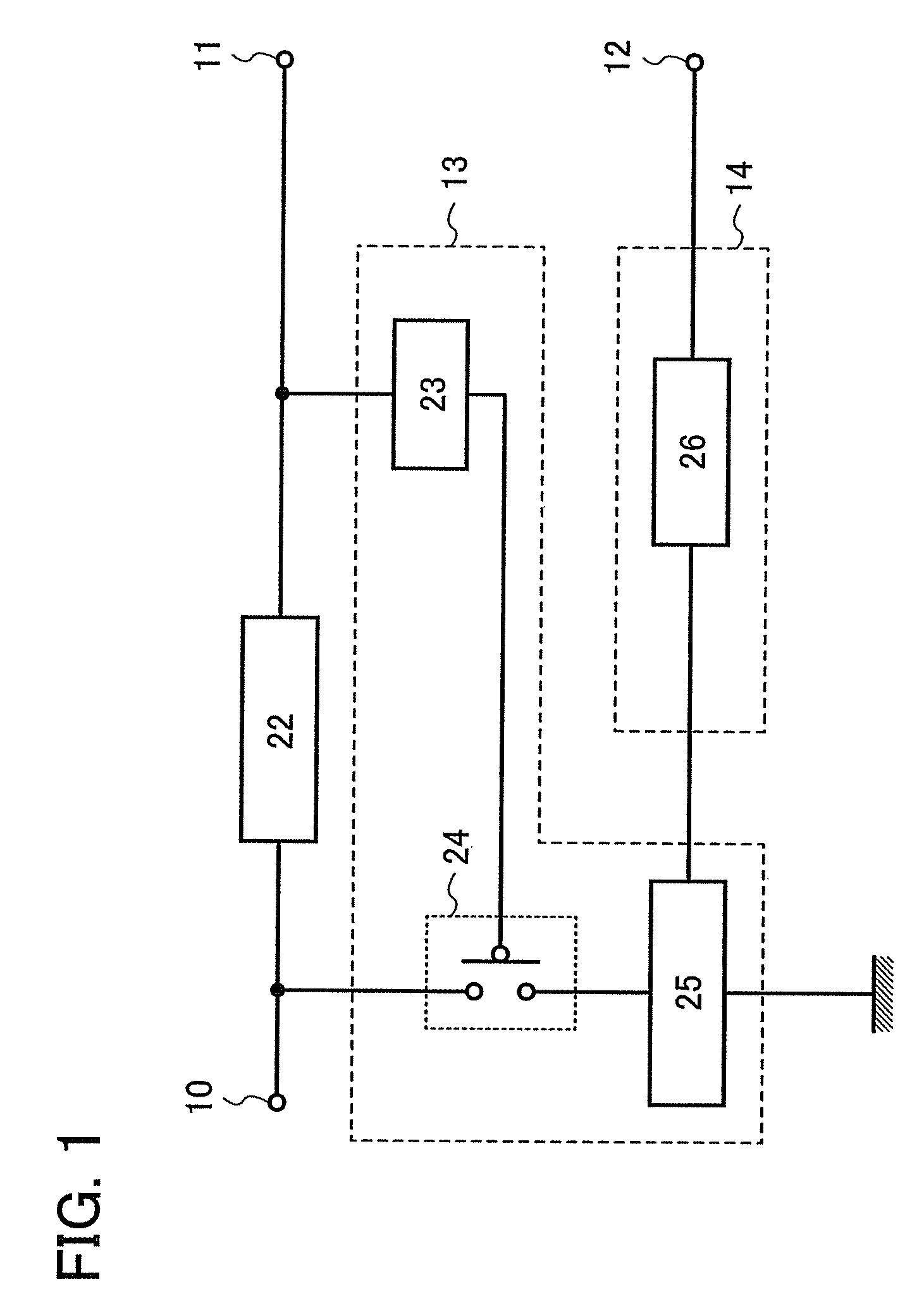
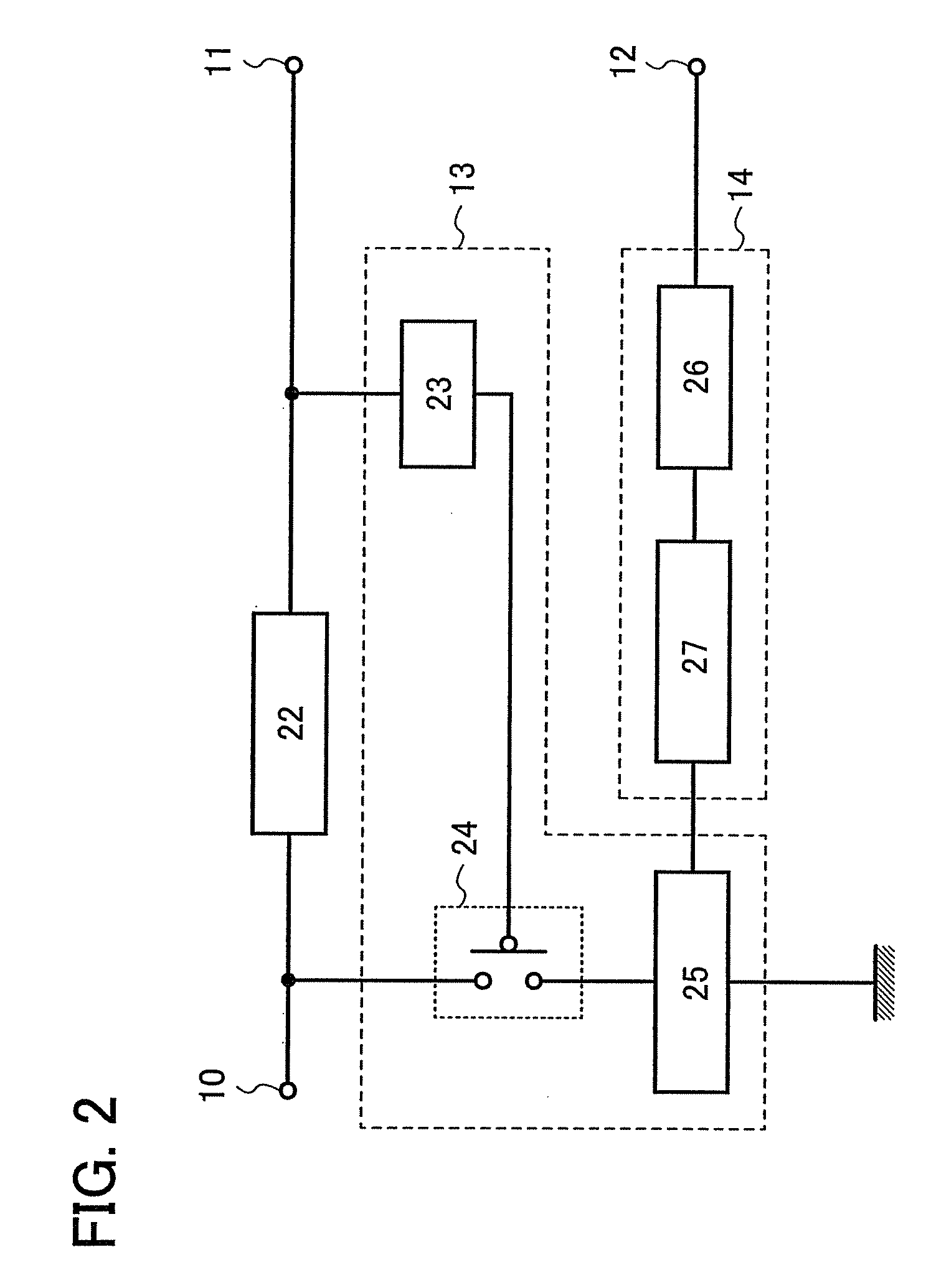
[0048]A semiconductor device described in this embodiment mode includes an input portion 10; a first DC converter circuit 22; a limiter circuit 13 including a first detecting circuit 23, a switching element 24, and a second DC converter circuit 25; and a charging circuit 14 including a battery 26 (see FIG. 1). A direct-current voltage, after being converted by the first DC converter circuit 22, is output to a first output portion 11, and electric power of the battery 26 is supplied to a circuit connected to an output portion 12.
[0049]The input portion 10 can, for example, be connected to an antenna, where electric power received by the antenna is supplied thereto.
[0050]The first DC converter circuit 22 converts an alternating-current voltage that is output from the input portion 10 into a direct-current voltage to be output to the f...
embodiment mode 2
[0076]In this embodiment mode, the case where the semiconductor device of the present invention is provided as a wireless tag (also called an RFID (Radio Frequency Identification) tag, an IC (Integrated Circuit) tag, an IC chip, an RF tag, or an electronic tag) which can communicate data wirelessly is described using drawings.
[0077]A semiconductor device described in this embodiment mode includes an antenna 40; the first DC converter circuit 22; the limiter circuit 13; the charging circuit 14; a modulating circuit 28 which modulates encoded data; a demodulating circuit 29 which digitalizes a signal received from the antenna 40; a constant voltage circuit 30 which makes an output voltage of the first DC converter circuit 22 a constant voltage; a clock generating circuit 31; an encoding circuit 32; a controller circuit 33; a judging circuit 34; and a memory 35 (see FIG. 3). Note that the limiter circuit 13 includes the first detecting circuit 23, the switching element 24, and the seco...
embodiment mode 3
[0096]A semiconductor device described in this embodiment mode includes the first DC converter circuit 22; the limiter circuit 13; the charging circuit 14; a first constant voltage circuit 54; a second constant voltage circuit 55; and a first discharge controller circuit 201. Note that the limiter circuit 13 includes the first detecting circuit 23, the switching element 24, and the second DC converter circuit 25, the charging circuit 14 includes the battery 26, and the first discharge controller circuit 201 includes a second detecting circuit 43, a switching element 56, a switching element 57, and the buffer 36 (see FIG. 6).
[0097]Operation of the semiconductor device described in this embodiment mode is described below. Note that, in the description hereinafter, when the first discharge controller circuit 201 does not operate, the switching element 56 is maintained at the ON state and the switching element 57 is maintained at the OFF state.
[0098]First, an alternating-current voltage...
PUM
 Abstract
Description
Claims
Application Information
 - R&D
- Intellectual Property
- Life Sciences
- Materials
- Tech Scout
- Unparalleled Data Quality
- Higher Quality Content
- 60% Fewer Hallucinations
Browse by: Latest US Patents, China's latest patents, Technical Efficacy Thesaurus, Application Domain, Technology Topic, Popular Technical Reports.
© 2025 PatSnap. All rights reserved.Legal|Privacy policy|Modern Slavery Act Transparency Statement|Sitemap|About US| Contact US: help@patsnap.com


