
Quantum cascade laser

a laser and quantum cascade technology, applied in lasers, lasers, semiconductor lasers, etc., can solve problems such as inability to use, and achieve the effect of reducing production yield and reliability, and suppressing transmutation and deterioration

Active Publication Date: 2016-03-01
HAMAMATSU PHOTONICS KK
View PDF5 Cites 1 Cited by
  • Summary
  • Abstract
  • Description
  • Claims
  • Application Information

AI Technical Summary

Benefits of technology

[0013]In a case where the film thickness of the reflection control film is adequately thin, even when applying coating onto the entire surface of the laser bar end face, it is possible to easily divide it into a single device without causing damage such as peeling or cracks to the reflection control film. On the other hand, in a case of a thick reflection control film corresponding to a long wavelength region, at the time of cleaving it into a single device, the reflection control film is not segmented along with a semiconductor base material, that causes burrs, peeling, or the like. Further, at the time of mounting the laser device onto the sub-mount, cracks and the like are caused in the reflection control film by stress. Such transmutation and deterioration in a reflection control film in the manufacturing process of the laser device causes a lowering in production yield and reliability of the laser device.
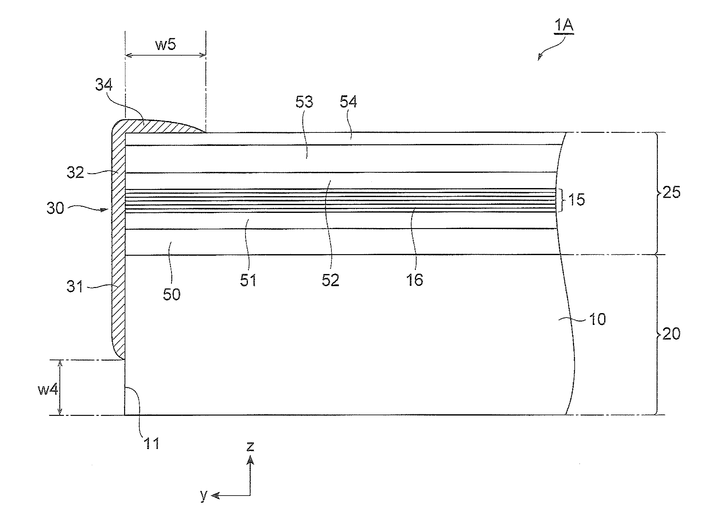
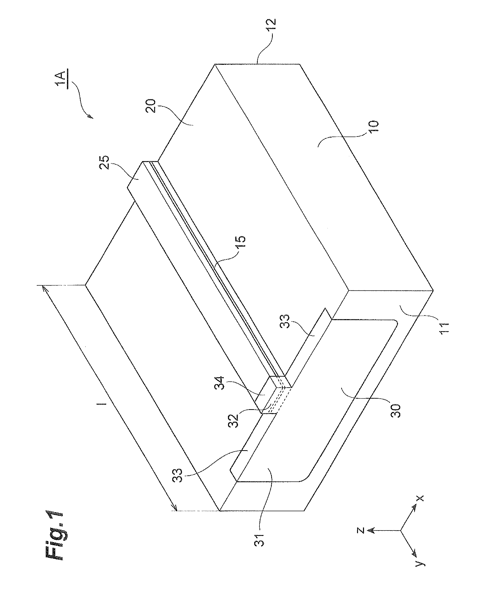
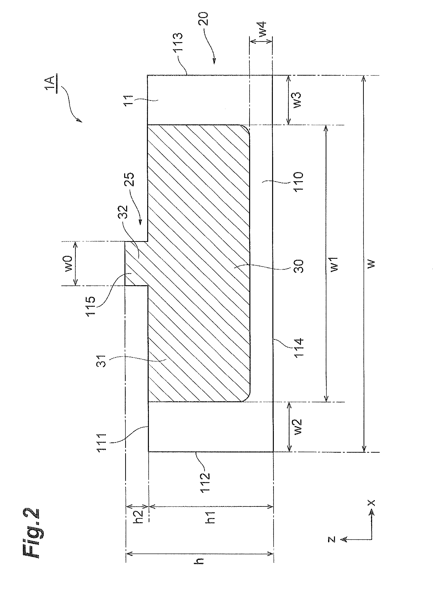
[0018]In this way, in accordance with the configuration in which a reflection control film is not formed on regions near the three sides of the two lateral sides and the one lower side of the base end face, it is possible to suppress transmutation and deterioration in a reflection control film due to burrs, peeling, cracks, and the like being caused in the manufacturing process of a laser device. Accordingly, it is possible to realize a quantum cascade laser in which a laser oscillation mode is preferably controlled by the reflection control film without lowering production yield and reliability due to deterioration in a reflection control film.
[0019]In accordance with the quantum cascade laser of the present invention, a ridge structure which has the base portion including the semiconductor substrate, and the ridge portion including the active layer is made, the reflection control film is formed from the ridge end face including the end portion of the active layer over the base end face, on at least the first end face which is one of the two end faces located in the resonating direction for light with a predetermined wavelength generated in the active layer, and on the base end face, the reflection control film is formed on a region other than a region with a predetermined width from a second side, a region with a predetermined width from a third side, and a region with a predetermined width from a fourth side, with respect to the second side and the third side adjacent to a first side on the ridge portion side of the base end face, and the fourth side facing the first side, thereby it is possible to suppress transmutation and deterioration in the reflection control film in the manufacturing process of a laser device.

Problems solved by technology

Meanwhile, in a long-wavelength region with a wavelength of 7 μm or more, because absorption of light is high, it is not possible to use Al2O3.

Method used


Image

  • Quantum cascade laser
  • Quantum cascade laser
  • Quantum cascade laser

Examples


Embodiment Construction

[0033]Hereinafter, an embodiment of a quantum cascade laser according to the present invention will be described in detail with reference to the drawings. In the description of the drawings, the same components are attached with the same reference symbols, and overlapping description will be omitted. Moreover, the dimensional ratios in the drawings are not always equal to those in the description.

[0034]FIG. 1 is a perspective view schematically showing a configuration of an embodiment of a quantum cascade laser according to the present invention. Further, FIG. 2 is a front view showing the configuration of the quantum cascade laser shown in FIG. 1. Further, FIG. 3 is a side sectional view showing the configuration of the quantum cascade laser shown in FIG. 1. Here, in FIG. 3, a side sectional view along the center line of a ridge portion in a ridge structure of a laser device is shown. Further, in the following respective diagrams, the xyz coordinate systems are shown for convenienc...


PUM


Abstract

A quantum cascade laser includes a semiconductor substrate, and an active layer being provided on the substrate, and having a cascade structure in which quantum well emission layers and injection layers are alternately laminated, and the laser has a base portion including the substrate, and a stripe-shaped ridge portion including the active layer. Further, a reflection control film is formed from a ridge end face over a base end face on an end face in a resonating direction of the laser, and, on the base end face, for a second side and a third side adjacent to a first side on the ridge portion side of the base end face, and a fourth side facing the first side, the reflection control film is formed on a region other than regions near those three sides with predetermined widths.

Description

BACKGROUND OF THE INVENTION[0001]1. Field of the Invention[0002]The present invention relates to a quantum cascade laser using intersubband transition in a quantum well structure.[0003]2. Related Background Art[0004]Light with a mid-infrared wavelength region (for example, wavelength of 3 to 30 μm) is an important wavelength region in the field of spectroscopy analysis. As a high-performance semiconductor light source in this wavelength region, in recent years, quantum cascade lasers (QCL) have gained attention (for example, refer to Patent Document 1).[0005]A quantum cascade laser is a monopolar type laser device which uses a level structure including subbands formed in a semiconductor quantum well structure and generates light by means of intersubband electron transition, and can realize high efficiency and high-output operations by multistage cascade-coupling of quantum well emission layers which are formed by quantum well structures and become active regions. Further, this casca...

Claims


Application Information

Patent Timeline
Patent Type & Authority Patents(United States)
IPC IPC(8): H01S5/34H01S5/22H01S5/02H01S5/028
CPCH01S5/3401H01S5/028H01S5/0281H01S5/0285H01S5/0286H01S5/0287H01S5/34H01S5/0207H01S5/22
Inventor SUGIYAMA, ATSUSHIEDAMURA, TADATAKAAKIKUSA, NAOTA
Owner HAMAMATSU PHOTONICS KK
Learn More