Optical cable having forming tape and rip cords

a technology of optical cables and forming tapes, applied in the field of optical cables, can solve the problems of difficult dividing of forming pipes 2, and achieve the effect of not always showing excellent subsequent dividing of optical cables

Inactive Publication Date: 2004-07-06
THE FUJIKURA CABLE WORKS LTD +1
View PDF11 Cites 37 Cited by
  • Summary
  • Abstract
  • Description
  • Claims
  • Application Information

AI Technical Summary

Benefits of technology

The dividable forming pipe 2 is made by continuously fashioning two slightly narrow-width laminate tapes so that each has a semi-circular shape in cross section, and then apposing these together. The two seams of forming pipe 2 can simply face one another, may be slightly overlapped, or may face each other with a slight spacing in between. An adhesive tape such as used in a conventional forming pipe is not employed here, so that the forming pipe 2 can be easily divided into two pieces when subsequently dividing the optical fiber.
When subsequently dividing an optical cable of this design, the rip cords 6 are pulled to tear open the sheath 4. As a result, the forming pipe 2, which was already split into two pieces, is divided each part remaining adhered to the respective portions of the sheath 4. As a result, the division of the sheath 4 and forming pipe 2 is carried out in a single stroke, and the optical ribbon core laminate 1 in the inside of the forming pipe 2 can be exposed quickly and easily.
Moreover, since the adhesive tape employed in convention optical cables is not necessary, fabrication of the optical cable is simplified and production costs are reduced.

Problems solved by technology

However, it can be difficult to divide the forming pipe 2 due to its high resistance to tearing, or because it adheres to the sheath 4, for example.
In other words, this optical cable does not always demonstrate excellent subsequent dividing.

Method used


Image

  • Optical cable having forming tape and rip cords
  • Optical cable having forming tape and rip cords
  • Optical cable having forming tape and rip cords

Examples


Embodiment Construction

Preferred embodiments of the present invention will now be explained in detail using the accompanying figures. Note that parts which have the same structure or function as in the conventional optical cable shown in FIG. 9 will be assigned the same numeric symbol and an explanation thereof will be omitted.

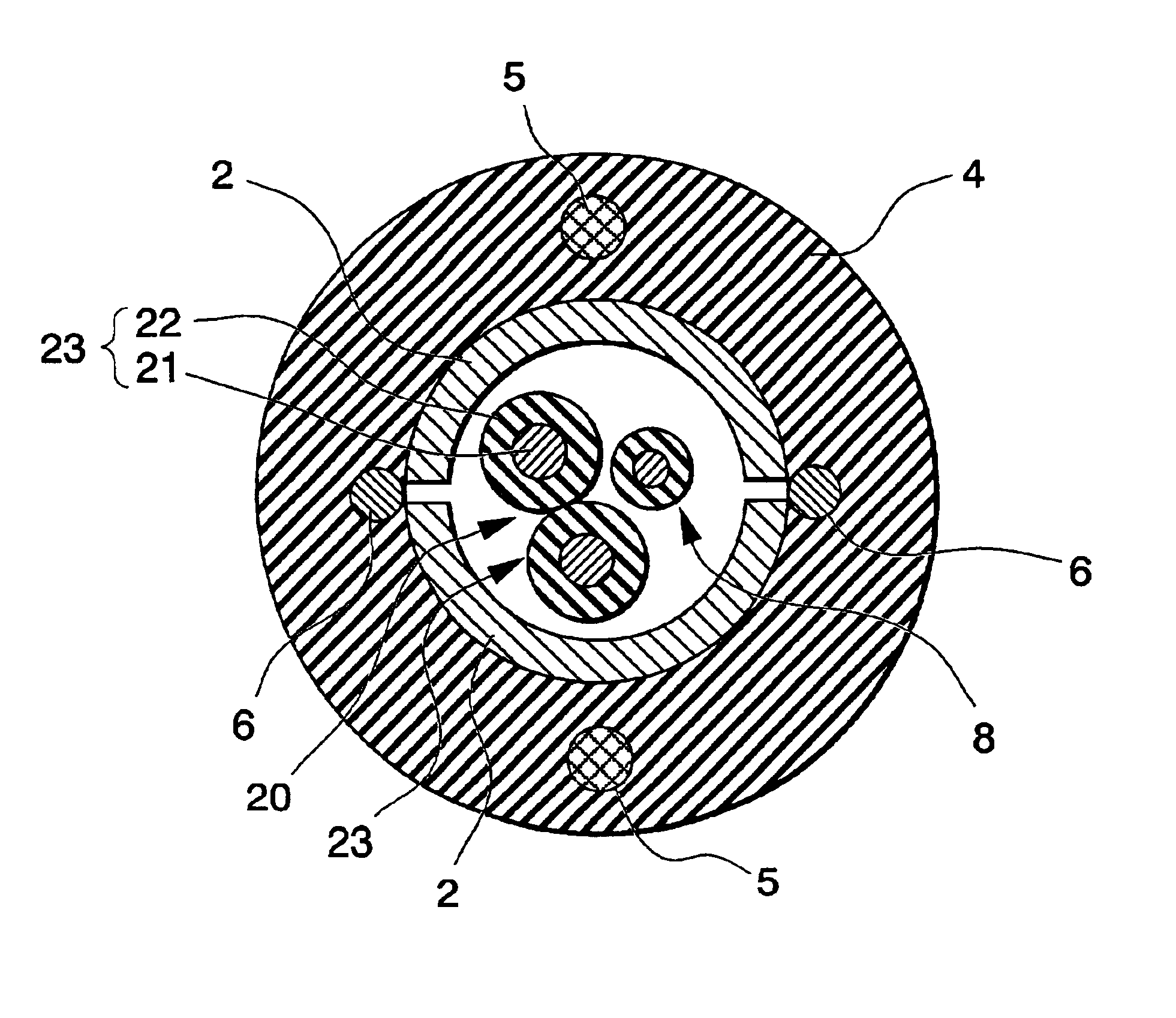
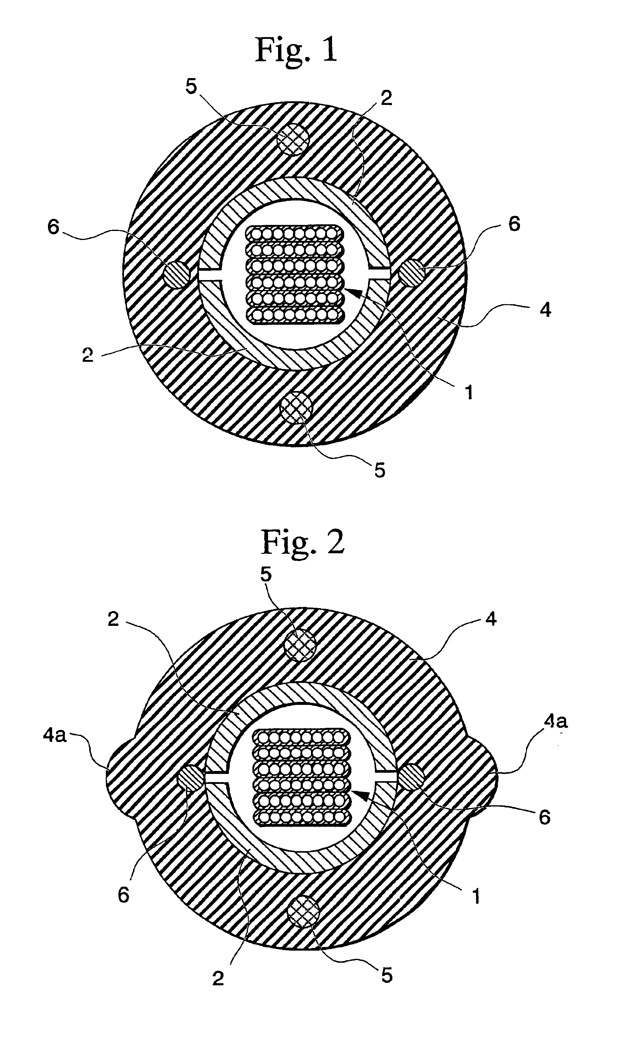
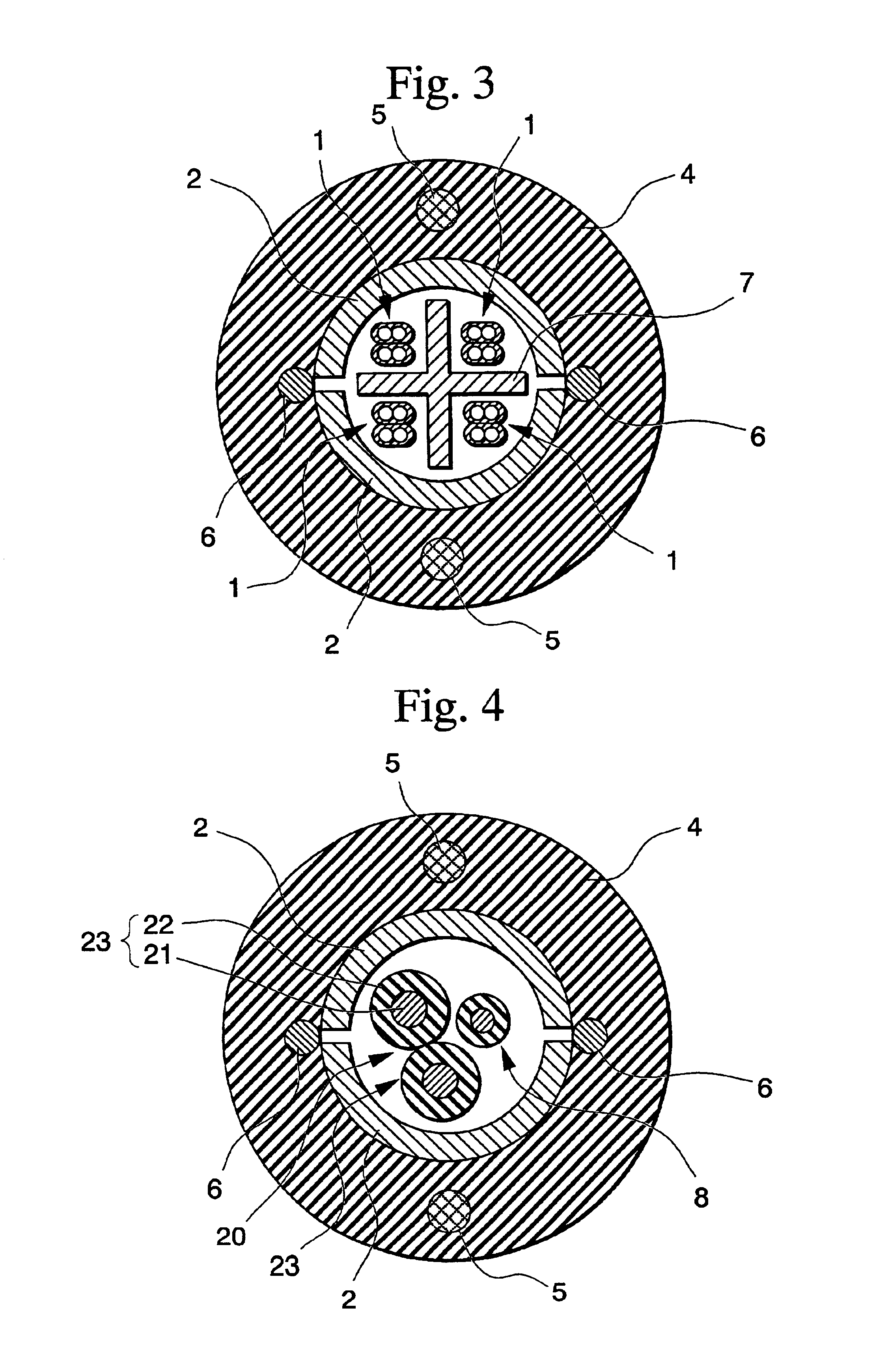
FIG. 1 shows an example of the optical cable according to the present invention. The optical cable of this example differs from the conventional optical cable shown in FIG. 9 in that the forming pipe 2 can be divided in half along its longitudinal direction, there is no adhesive tape 3, and rip cords 6 are disposed inside of the sheath 4 near the seams of the dividable forming pipe 2.

The dividable forming pipe 2 is made by continuously fashioning two slightly narrow-width laminate tapes so that each has a semi-circular shape in cross section, and then apposing these together. The two seams of forming pipe 2 can simply face one another, may be slightly overlapped, or may face each ot...


PUM

PropertyMeasurementUnit
tensionaaaaaaaaaa
hot-meltaaaaaaaaaa
structureaaaaaaaaaa

Abstract

The present invention's optical cable is provided with optical fibers, a forming pipe for housing the optical fibers, a sheath provided around the forming pipe, and at least one pair of rip cords embedded in the sheath. The forming pipe is formed of a plurality of tapes so that it is dividable along its longitudinal direction. When dividing the optical cable, the rip cords are pulled to tear open the sheath, and the already split forming pipe is divided while staying adhered to the respective parts of the sheath. As a result, the division of the sheath and the forming pipe is carried out in one stroke, so that the optical fibers inside the forming pipe can be exposed easily and quickly.

Description

1. Field of the InventionThe present invention relates to an optical cable that can be divided later with improved ease.2. Background ArtAn optical cable having a structure like that shown in FIG. 9 has been proposed recently.In FIG. 9, numeral 1 indicates an optical ribbon core laminate in which multiple layers of optical fiber ribbon have been laminated together. This optical ribbon core laminate 1 is not fixed completely in place inside of the forming pipe 2, but rather is housed with an interval of spacing between itself and forming pipe 2.This forming pipe 2 is formed into the shape of a pipe by employing a pipe forming method in which tape, consisting of a rigid plastic film like polyester, polypropylene, polyethylene, polyamide, or fiber reinforced plastic (FRP), is continuously fashioned into a pipe shape. The seams running along the longitudinal direction of this forming pipe 2 are then joined together by meaning of adhesive tape 3.The forming pipe 2 is covered with a sheat...

Claims


Application Information

Patent Timeline
Patent Type & Authority Patents(United States)
IPC IPC(8): G02B6/44H01B11/00
CPCG02B6/4495G02B6/4431
Inventor OKADA, NAOKIHASHIMOTO, YOSHIOYAMANAKA, MASAYOSHISUEMATSU, MICHIOMIYAMOTO, MATSUHIROSATOH, YOSHIYASUWATANABE, KOICHIROHOGARI, KAZUO
Owner THE FUJIKURA CABLE WORKS LTD
Why Eureka
Try Eureka