Introducer Sheath Assembly with Hub and Method of Joining a Hub to a Sheath Tube

a technology of hub and sheath tube, which is applied in the field of flexible medical tubing and components, can solve the problems of inherent weakness of tubes, and achieve the effects of strong joint, easy splitting, and inherent weakness

Active Publication Date: 2009-07-30
MEDICAL COMPONENTS INC
View PDF23 Cites 37 Cited by
  • Summary
  • Abstract
  • Description
  • Claims
  • Application Information

AI Technical Summary

Benefits of technology

[0011]In one practical embodiment, the method provides an assured joint of an introducer sheath tube of polytetrafluoroethylene (PTFE) and a liner and a hub component (or components) of a different plastic such as polyethylene.
[0013]An introducer assembly of the present invention may be made using the present inventive method where the hub component is molded to the sheath tube proximal end, where the hub comprises two halves initially joined to each other at frangible seams along opposite sides of the sheath tube, such that the hub component can be easily split for easy removal of the introducer sheath assembly from a catheter after insertion into a patient. The sheath tube has at least one pair of holes adjacent the proximal end through which the hub halves are formed with joints extending through the sheath tube holes affixing them to a liner within the sheath tube, so that each hub half remains assuredly affixed to a respective side of the sheath tube. Also, preferably, the liner includes a proximal end portion protruding beyond the sheath tube proximal end to which the hub component integrally joins, as well, and may include notches into the proximal end to initiate eventual sheath assembly splitting. The introducer sheath tube has inherent lines of weakness, and additionally may have slits partially therealong, to continue the splitting entirely along the sheath tube, resulting from the PTFE material. Other sheath tube materials may be used but scoring of an opposed pair of seams therealong would expected to be provided to facilitate sheath tube splitting.

Problems solved by technology

The introducer sheath tube has inherent lines of weakness, and additionally may have slits partially therealong, to continue the splitting entirely along the sheath tube, resulting from the PTFE material.

Method used


Image

  • Introducer Sheath Assembly with Hub and Method of Joining a Hub to a Sheath Tube
  • Introducer Sheath Assembly with Hub and Method of Joining a Hub to a Sheath Tube
  • Introducer Sheath Assembly with Hub and Method of Joining a Hub to a Sheath Tube

Examples


Embodiment Construction

[0027]In the drawings, like numerals indicate like elements throughout. Certain terminology is used herein for convenience only and is not to be taken as a limitation on the present invention. The terms “distal” and “proximal” refer, respectively, to directions closer to and away from the insertion tip of a catheter in an implantable catheter assembly. The terminology includes the words specifically mentioned, derivatives thereof and words of similar import. The embodiments illustrated below are not intended to be exhaustive or to limit the invention to the precise form disclosed. These embodiments are chosen and described to best explain the principle of the invention and its application and practical use and to enable others skilled in the art to best utilize the invention.

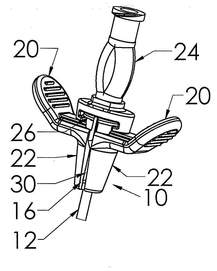
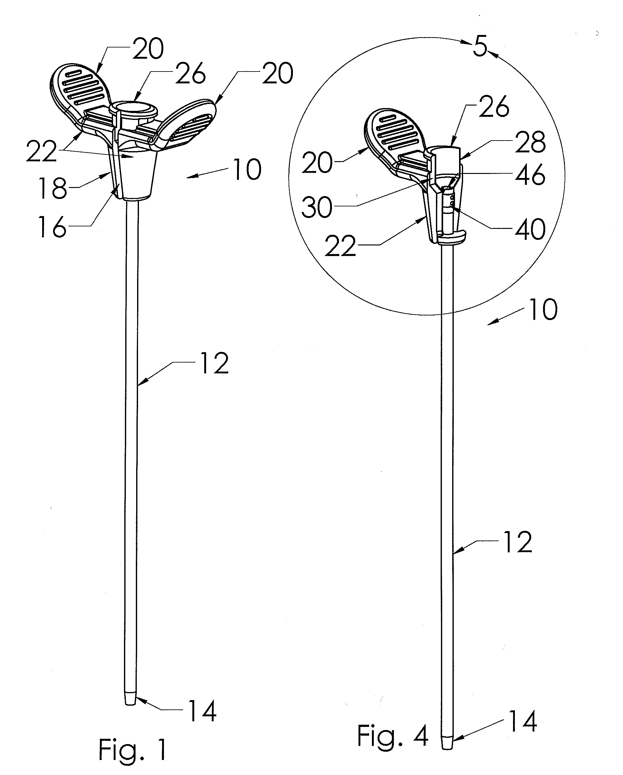
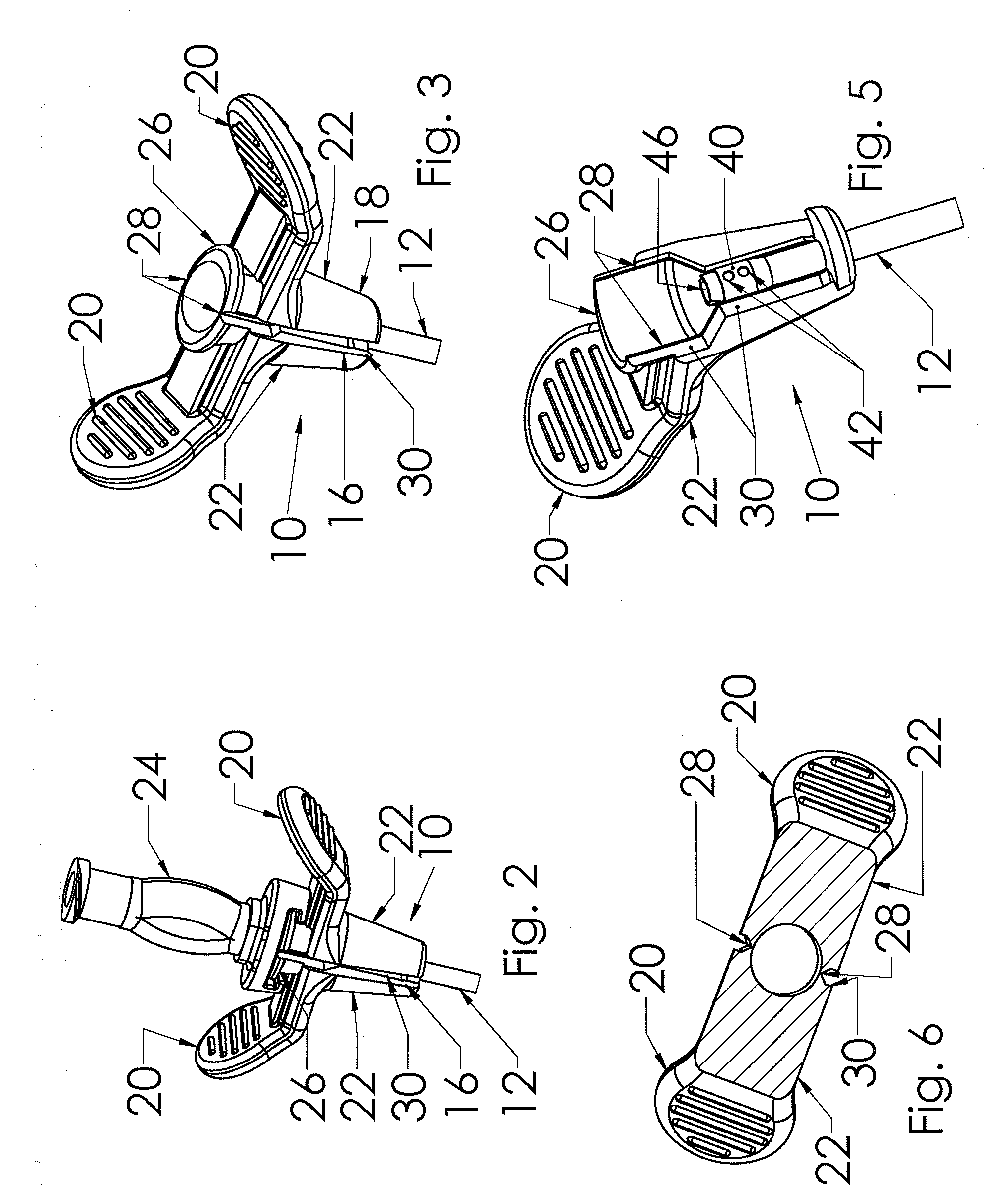
[0028]In FIG. 1, introducer assembly 10 of the present invention includes an elongate sheath tube 12 having a distal end 14 and a passageway extending therethrough, with a hub component 16 affixed to the proxima...


PUM

PropertyMeasurementUnit
inner diameteraaaaaaaaaa
diameteraaaaaaaaaa
flexibleaaaaaaaaaa

Abstract

A tearaway introducer sheath assembly (10) for use in implantation of a catheter into a patient, having an elongated polytetrafluoroethylene sheath tube (12) and a proximal polyethylene hub component (16). The hub comprises two halves (22) insert molded about the sheath tube proximal end and joined to each other by frangible webs (28) enabling manual splitting. At least one pair of opposed holes (42) is formed through the tube proximal end portion 44, and a polyethylene liner (46) is inserted into the tube's proximal end portion. The polyethylene flows into the at least one pair of holes (42) to fuse with the liner, establishing a pair of physical joints (50′) integrally joining the liner (46) to a respective hub half (22). Upon manual splitting of the hub halves, the sheath tube easily splits along its length as a result of a property of the polytetrafluoroethylene material.

Description

CROSS-REFERENCE TO RELATED APPLICATIONS[0001]This application claims priority from U.S. Provisional Patent Application Ser. No. 61 / 062,714, filed Jan. 29, 2008.FIELD OF THE INVENTION[0002]This relates to the field of medical devices, and more particularly to flexible medical tubing and components affixed thereto.BACKGROUND OF THE INVENTION[0003]Catheters are often used for the delivery and withdrawal of fluids to and from a blood vessel in a patient, respectively. The fluids may be medication that is administered to the patient, or blood that is withdrawn from the patient. The catheter may also be used for hemodialysis, in which blood is withdrawn from the patient, purified and returned simultaneously through respective lumens of the catheter, and much of the catheter remains within the patient's vasculature for an extended period of time for repeated treatments.[0004]Typically, to insert a catheter into a blood vessel, the blood vessel is located by known methods. An aspirating nee...

Claims


Application Information

Patent Timeline
Patent Type & Authority Applications(United States)
IPC IPC(8): A61M25/01B23P11/00
CPCA61M25/0014Y10T29/49826A61M25/0668A61M2039/1061B29C65/02B29C65/76B29C66/71B29C66/712B29C2793/0036B29K2023/06B29K2027/18B29L2023/007A61M25/0097B29C66/5344B29C65/56
Inventor NARDEO, MAHASESPENCE, TREVOR
Owner MEDICAL COMPONENTS INC
Why Eureka
Try Eureka