Shadow mask assemblies and reusing methods of shadow mask assemblies thereof

Active Publication Date: 2018-10-11
SHENZHEN CHINA STAR OPTOELECTRONICS TECH CO LTD
View PDF0 Cites 8 Cited by
  • Summary
  • Abstract
  • Description
  • Claims
  • Application Information

AI Technical Summary

Benefits of technology

[0025]In the electronic device and the backlight control circuit of the present disclosure, when the electronic device enters the three-dimensional mode, the feedback voltage adjustment unit controls to reduce the feedback terminal voltage transmitted to the feedback terminal of the driving chip, so that the feedback terminal voltage of the feedback terminal of the driver chip is smaller than the reference voltage of the reference voltage terminal

Problems solved by technology

However, the existing implementation in the three-dimensional mo

Method used


Image

  • Shadow mask assemblies and reusing methods of shadow mask assemblies thereof
  • Shadow mask assemblies and reusing methods of shadow mask assemblies thereof
  • Shadow mask assemblies and reusing methods of shadow mask assemblies thereof

Examples


Embodiment Construction

[0029]The present disclosure will now be combined with the implementation of the drawings, were a clear example of the technical solutions of the present disclosure, a complete description of, obviously, the described embodiments are only part of the embodiments of the present disclosure, but not all embodiments example. Based on the embodiments of the present disclosure, those of ordinary skill in making all other embodiments no creative effort obtained are within the scope of protection of the present disclosure.

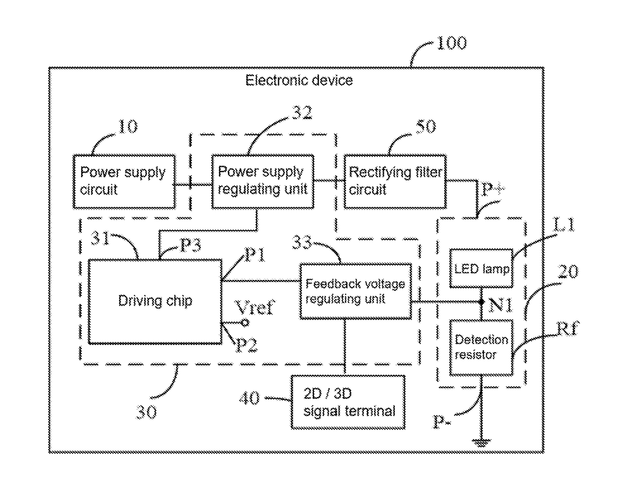
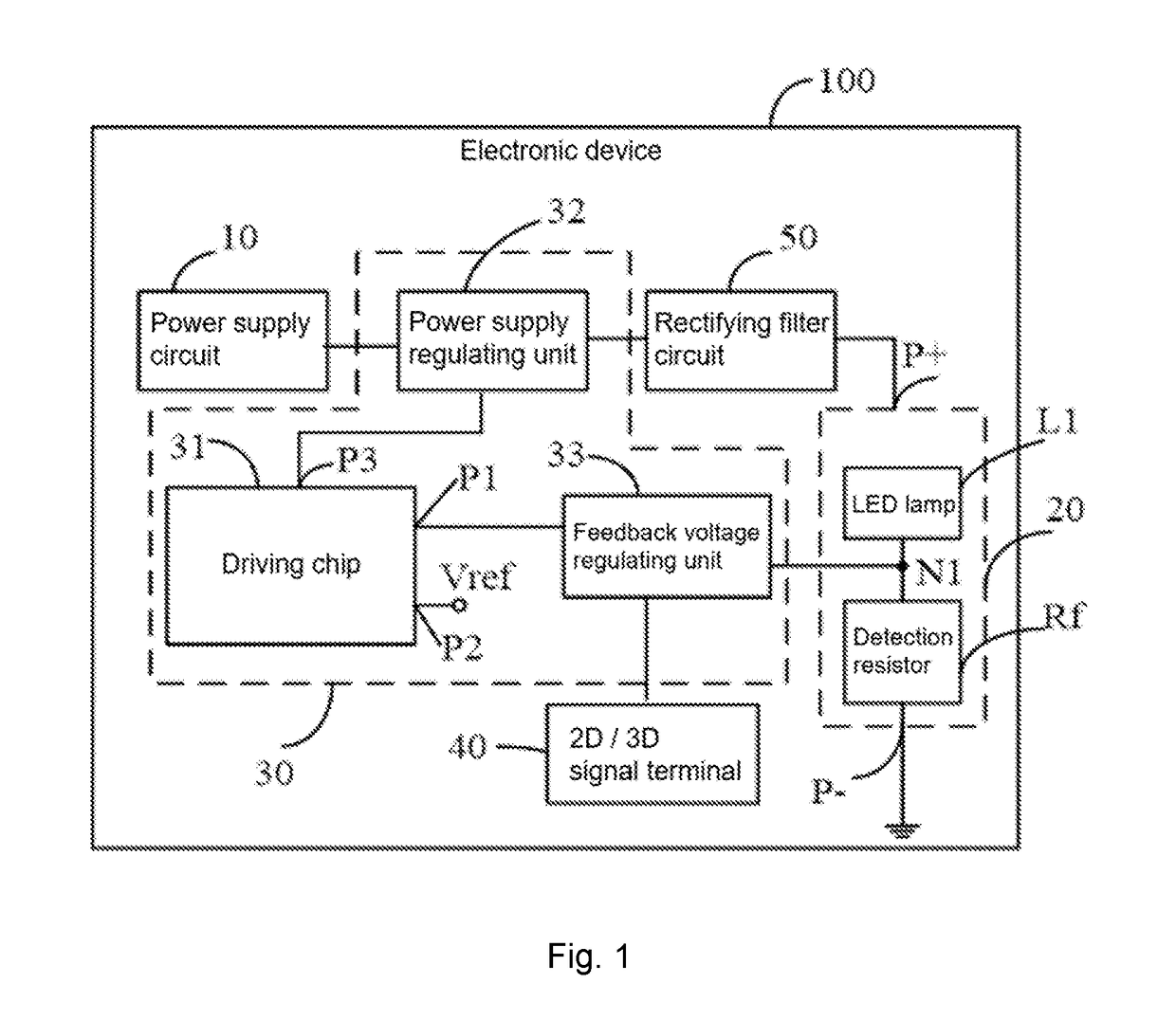
[0030]Please refer to FIG. 1, FIG. 1 is a block diagram of the electronic device of the present disclosure 100 (hereinafter referred to as the electronic device 100). The electronic device 100 includes a power supply circuit 10, a LED (light-emitting diode) module 20, a backlight module 30 and a 2D / 3D signal terminal 40. The backlight control circuit 30 is used to adjust the current of the LED module 20 of the electronic device 100.

[0031]The LED module 20 includes a positi...


PUM


Abstract

The present disclosure discloses a backlight control circuit for adjusting a current of an LED module of an electronic device including a driving chip having a feedback terminal and a reference voltage terminal, a feedback voltage regulating unit, and a power supply regulating unit; the feedback voltage regulating unit is also connected to the 2D/3D signal terminal, the feedback terminal voltage is controlled so that the feedback terminal voltage of the feedback terminal of the driving chip is lower than the reference voltage of the reference voltage terminal when receiving the three-dimensional signal generated at the 2D/3D signal terminal. The present application also provides an electronic device. With the scheme of the present application, the current of the LED module can be increased when the electronic device is in the three-dimensional mode.

Description

CROSS REFERENCE[0001]The present disclosure claims the priority of No. 201710039158.3, entitled “backlight control circuit and electronic device”, filed on Jan. 19, 2017, the disclosure of which is incorporated herein by reference in its entirety.FIELD OF THE DISCLOSURE[0002]The present disclosure relates to a control circuit, and more particularly to a backlight control circuit and an electronic device.BACKGROUND OF THE DISCLOSURE[0003]The current use of LED (light-emitting diode) as a backlight of electronic devices more and more. Current electronic devices such as televisions, computer displays, etc. can often work in 2D mode or 3D mode. At present, in the three-dimensional mode, the current flowing through the LED needs to be higher than the two-dimensional mode to provide sufficient backlight brightness in three-dimensional mode. Therefore, when the electronic device is operated in three-dimensional mode, it is necessary to increase the current of the LED, and when the electron...

Claims


Application Information

Patent Timeline
IPC IPC(8): G09G3/34G09G3/00
CPCG09G3/3406G09G3/003G09G2320/0646G09G2330/021G09G2320/0633G09G2320/064G09G2330/12
Inventor LI, WENDONG
Owner SHENZHEN CHINA STAR OPTOELECTRONICS TECH CO LTD
Why Eureka
Try Eureka