Switch

Active Publication Date: 2018-10-18
ALPS ALPINE CO LTD
View PDF0 Cites 2 Cited by
  • Summary
  • Abstract
  • Description
  • Claims
  • Application Information

AI Technical Summary

Problems solved by technology

With this configuration, the maximum size of the movable contact is limited by the bosses.
When the size of a tactile switch is reduced, the size

Method used


Image

  • Switch
  • Switch
  • Switch

Examples


Embodiment Construction

[0013]Embodiments of the present invention are described below with reference to the accompanying drawings. Throughout the specification and the drawings, the same reference number is assigned to components having substantially the same function and configuration, and repeated description of those components is omitted.

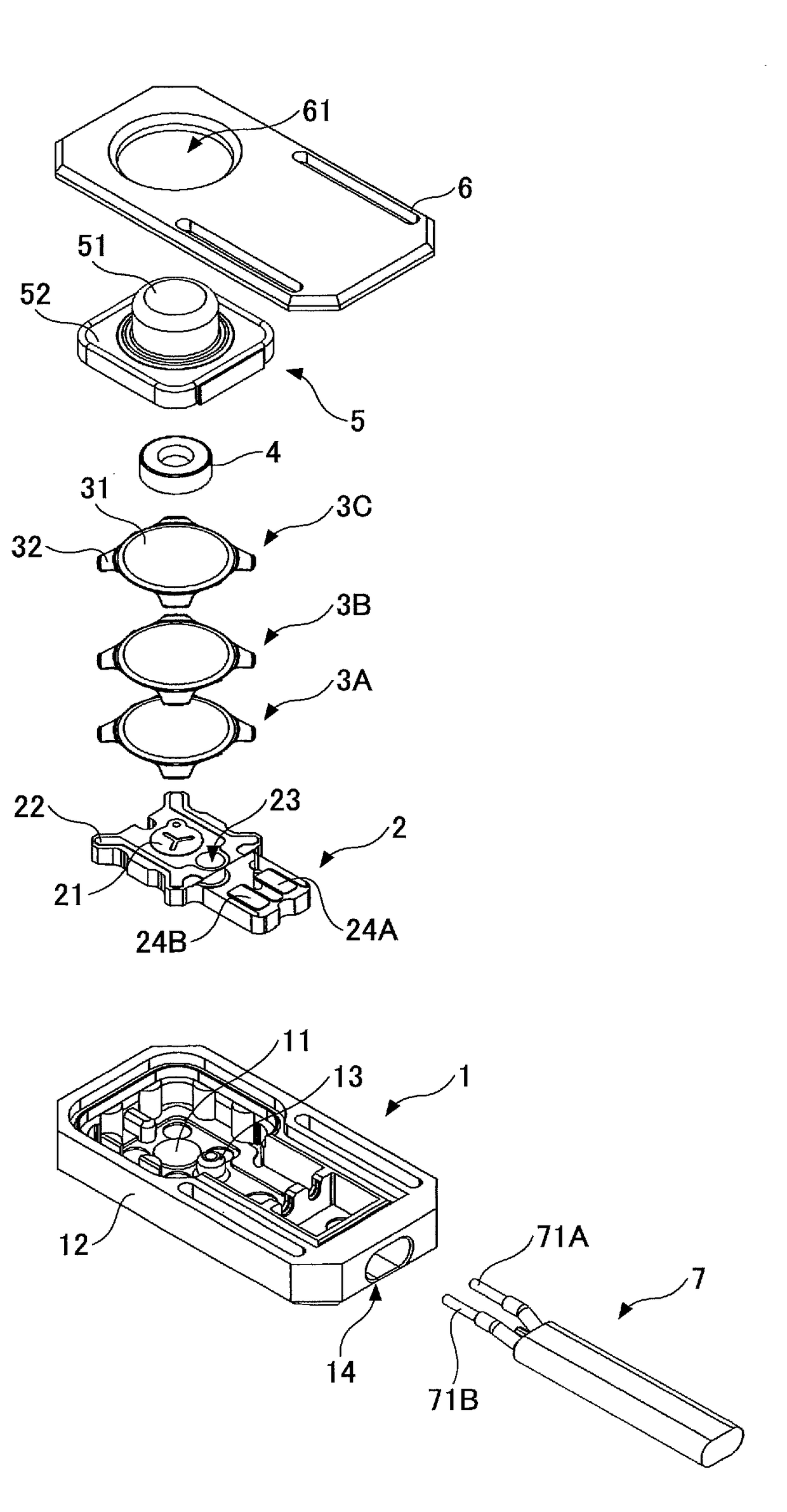
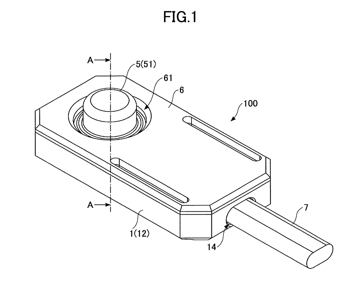
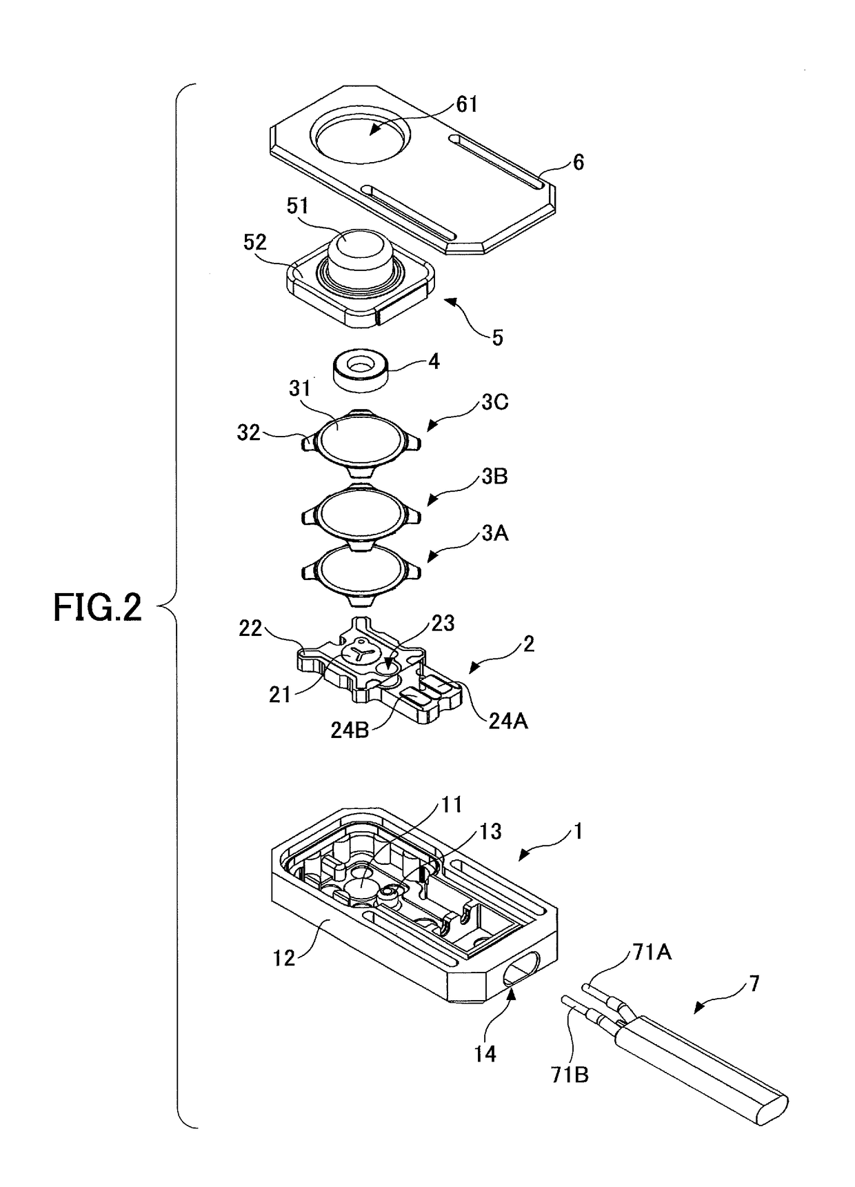
[0014]A switch 100 according to an embodiment is described with reference to FIGS. 1 through 7. The switch 100 is an example of a tactile switch. FIG. 1 is a perspective view of the switch 100. FIG. 2 is an exploded perspective view of the switch 100. As illustrated in FIGS. 1 and 2, the switch 100 includes a housing 1, a board 2, movable contacts 3A through 3C, a stem 4, an operation part 5, and a lid 6.

[0015]The housing 1 is made of a resin and constitutes the outer wall of the switch 100 together with the operation part 5 and the lid 6. As illustrated in FIG. 2, the housing 1 houses the board 2, the movable contacts 3A through 3C, the stem 4, and the operation part...


PUM


Abstract

A switch includes a housing including a bottom surface and a protrusion formed on the bottom surface, a board that is placed on the bottom surface of the housing and includes a fixed contact, the board and the protrusion being fitted together, a movable contact that is disposed to cover at least portions of the fixed contact and the protrusion and configured to be inverted, and an operation part that presses the movable contact toward the fixed contact.

Description

CROSS-REFERENCE TO RELATED APPLICATION[0001]The present application is based upon and claims the benefit of priority of Japanese Patent Application No. 2017-079417, filed on Apr. 13, 2017, the entire contents of which are incorporated herein by reference.BACKGROUND OF THE INVENTION1. Field of the Invention[0002]An aspect of this disclosure relates to a switch.2. Description of the Related Art[0003]A tactile switch includes a fixed contact provided on a board and a movable contact disposed above the movable contact. Tactile switches have come to be used for various purposes, and there is a demand for smaller tactile switches.[0004]In related-art tactile switches, bosses for fixing a board to a housing are disposed on the outer side of a movable contact (see, for example, Japanese Laid-Open Patent Publication No. 2014-071995). With this configuration, the maximum size of the movable contact is limited by the bosses. When the size of a tactile switch is reduced, the size of the movable...

Claims


Application Information

Patent Timeline
IPC IPC(8): H01H13/10H01H13/52H01H13/48
CPCH01H13/10H01H13/52H01H13/48H01H2205/004H01H13/06H01H2229/034H01H2229/05H01H2203/026H01H2215/03H01H9/04H01H2215/006H01H2221/05H01H2223/002
Inventor OHARA, HIROSHI
Owner ALPS ALPINE CO LTD
Why Eureka
Try Eureka