
Controlled axial displacement posterior chamber phakic intraocular lens

a phakic intraocular lens and control technology, applied in the field of visual deficiency treatment, can solve the problems of increased pressure in the anterior chamber of the eye, restricted horizontal force being applied to the footplates and haptics, so as to reduce the length of the pcpil, the effect of reducing the number of pcpil lengths

Inactive Publication Date: 2018-11-08
STAAR SURGICAL COMPANY INC
View PDF5 Cites 3 Cited by
  • Summary
  • Abstract
  • Description
  • Claims
  • Application Information

AI Technical Summary

Benefits of technology

[0011]In a general aspect, the present invention includes an improved design of the haptics and / or footplates of a PCPIL to minimize or eliminate axial displacement of the PCPIL when the PCPIL is placed under horizontal compression, such as occurs when the PCPIL is implanted in an eye. The improved PCPIL allows the initial axial displacement of the PCPIL to be independent of the overall length of the PCPIL, resulting in the axial displacement of the lens being minimized as the lens is horizontally compressed during implantation. Additionally, the improved PCPIL haptic and footplate design potentially reduces the number of PCPIL lengths that must be kept in inventory to treat a reasonable range of patients. Furthermore, the improvements allow the development of low axial displacement and high axial displacement PCPILs to meet individual patient needs.
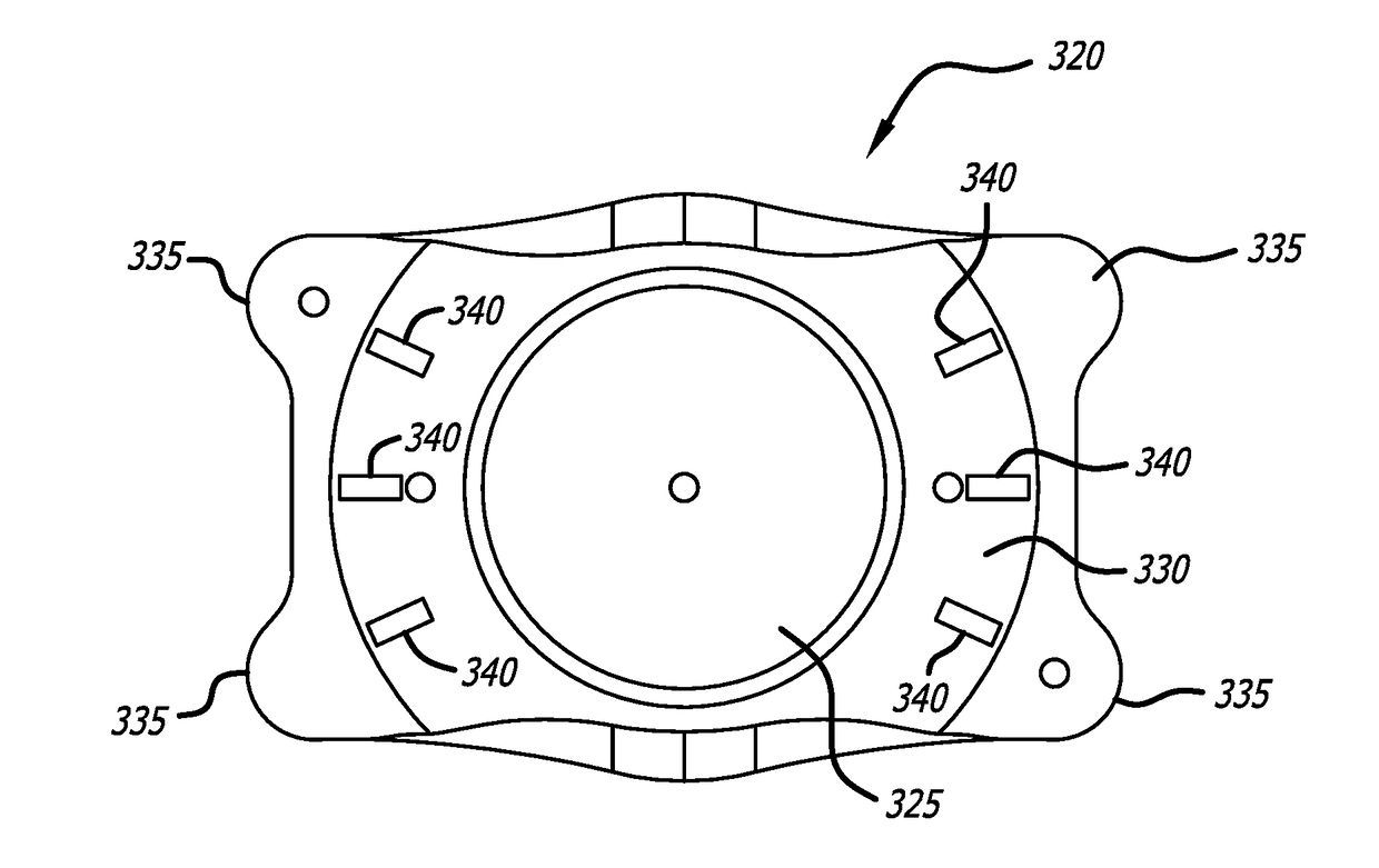
[0021]In another aspect, the present invention includes an improved posterior chamber phakic intraocular lens, comprising: an optic; a haptic body surrounding the optic, the haptic body having a posterior and an anterior surface, the posterior surface having a non-spherical curvature similar to the curvature of the crystalline lens of an eye; and at least two supporting elements, each supporting elements having a length and a proximal end mounted to the haptic body on a diametrically opposed side of the optic, each of the supporting elements also having a footplate disposed at a distal end of the haptic body. In another aspect, at least one of the at least two supporting elements has a distal end that is angled anteriorly with respect to the haptic body. In yet another aspect, the distal end of the at least one of the at least two supporting elements has an angulation configured to absorb compressive force applied to the at least two supporting elements so as to reduce anterior axial displacement of the optic resulting from application of the compressive force to the at least two supporting elements.

Problems solved by technology

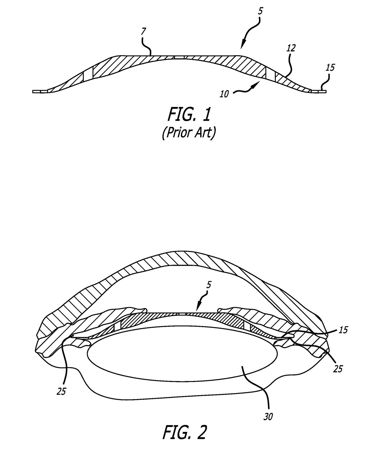
Implantation of the PCPIL into the eye typically results in a compressive, horizontal force being applied to the footplates and haptics of the lens by the eye.
This may be disadvantageous because such an axial displacement may cause, as an example, but not limited to, the anterior surface of the PCPIL pushing the iris of the eye anteriorly to the extent that draining of the aqueous through the angle of the eye could become restricted and the pressure in the anterior chamber of the eye could increase.
However, this method requires the implanting surgeon to accurately estimate the diameter of the sulcus of the eye, a region of the eye that is not directly visible from outside of the eye and that varies from patient to patient, and then select the appropriate PCPIL size, which can be difficult.
Moreover, if the PCPIL displaces axially in an uncontrolled manner when implanted, the positioning of the PCPIL within the eye may affect the precision of focus provided by the PCPIL as the effect of the lens is influenced by its proximity to other optical elements within the eye, including the cornea, the crystalline lens and the retina.
This may result in a less than optimal visual outcome after implantation.
While an axial displacement that is too great may cause other problems within the eye as well, a PCPIL with too little clearance above the crystalline lens may also be problematic, as such a PCPIL may then contact the crystalline lens.
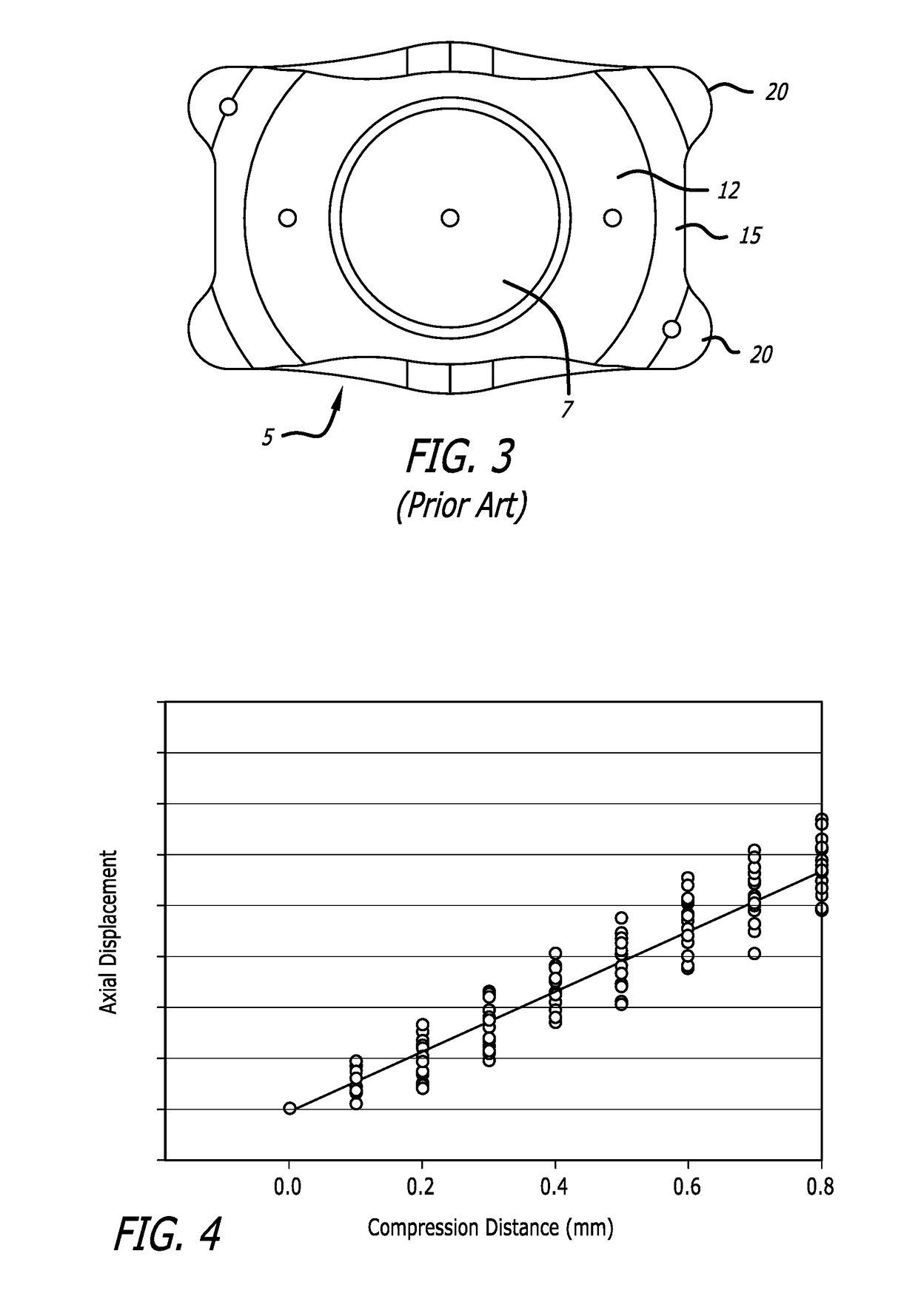
In many cases, however, the size of the eye and PCPIL cannot be identically matched, resulting in some residual compressive force on the haptics of the PCPIL, which causes the PCPIL to displace axially.

Method used


Image

  • Controlled axial displacement posterior chamber phakic intraocular lens
  • Controlled axial displacement posterior chamber phakic intraocular lens
  • Controlled axial displacement posterior chamber phakic intraocular lens

Examples


Embodiment Construction

[0048]In the following description, numerous specific details are set forth in order to provide a thorough understanding of the present invention. It will be apparent, however, to one of ordinary skill in the art, that the present invention may be practiced without these specific details. In other instances, well known components or methods have not been described in detail but rather in a block diagram, or a schematic, in order to avoid unnecessarily obscuring the present invention. Further specific numeric references such as “first driver,” may be made. However, the specific numeric reference should not be interpreted as a literal sequential order but rather interpreted that the “first driver” is different than a “second driver.” Thus, the specific details set forth are merely exemplary. The specific details may be varied from and still be contemplated to be within the spirit and scope of the present invention.

[0049]This invention comprises multiple elements of a PCPIL haptic desi...


PUM


Abstract

An improved posterior chamber phakic intraocular lens (PCPIL) is provided. The improved PCPIL incorporates one or more design elements that minimize or eliminate axial displacement of the PCPIL under horizontal compression.

Description

CROSS-REFERENCE TO RELATED APPLICATIONS[0001]This application is a divisional of U.S. patent application Ser. No. 15 / 166,117, filed May 26, 2016, and claims the benefit of priority to U.S. Provisional Application No. 62 / 166,226, filed on May 26, 2015, and to all of the applications in the chain, all of which are incorporated herein in their entireties by reference.BACKGROUND[0002]The invention is generally directed to the field of treatment of visual deficiency, such as myopia, hyperopia, and astigmatism, either alone, or in combination with myopia or hyperopia. More specifically, the invention is directed to an improved haptic and / or footplate for an posterior chamber phakic intraocular lens (PCPIL).[0003]As shown in FIG. 1, a PCPIL 5 intended to treat myopia or hyperopia, with or without astigmatism (also known as cylinder). PCPILs typically have a spherical power ranging from +15.0 Diopter (D) to −25.0 D with cylinder power with a magnitude up to about 10 D.[0004]A current PCPIL ...

Claims


Application Information

Patent Timeline
Patent Type & Authority Applications(United States)
IPC IPC(8): A61F2/16
CPCA61F2002/1699A61F2/161A61F2002/1689A61F2002/169A61F2/1629
Inventor PAUL, THOMAS R.OSSIPOV, ALEXITLAXCA, JOSE L.
Owner STAAR SURGICAL COMPANY INC
Learn More