Earth working machine whose working apparatus is displaceable out of its operating position using an onboard actuator
a technology of working apparatus and actuator, which is applied in the field of earth working machines to achieve the effect of avoiding or reducing the installation moment load
- Summary
- Abstract
- Description
- Claims
- Application Information
AI Technical Summary
Benefits of technology
Problems solved by technology
Method used
Image
Examples
first embodiment
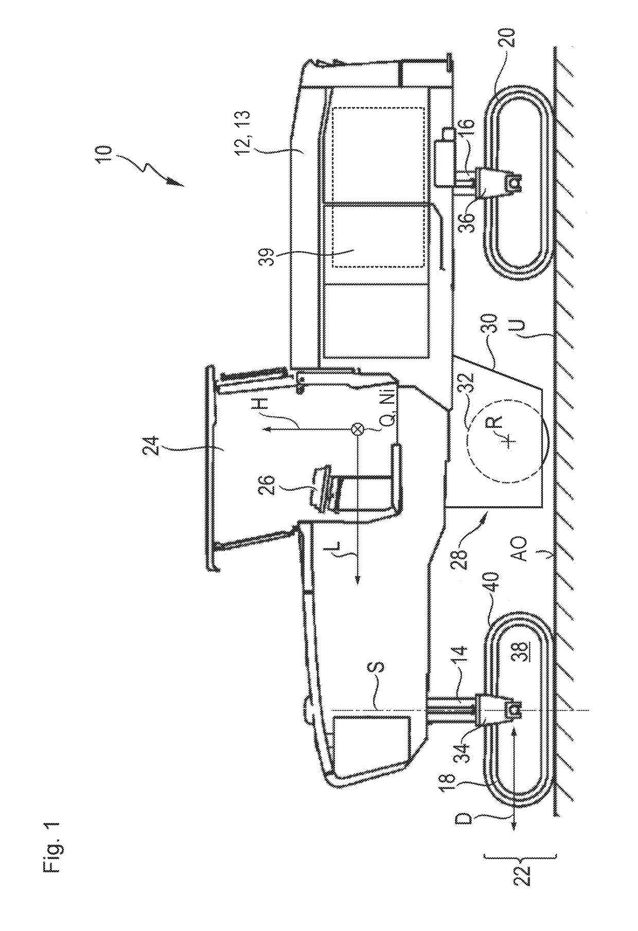
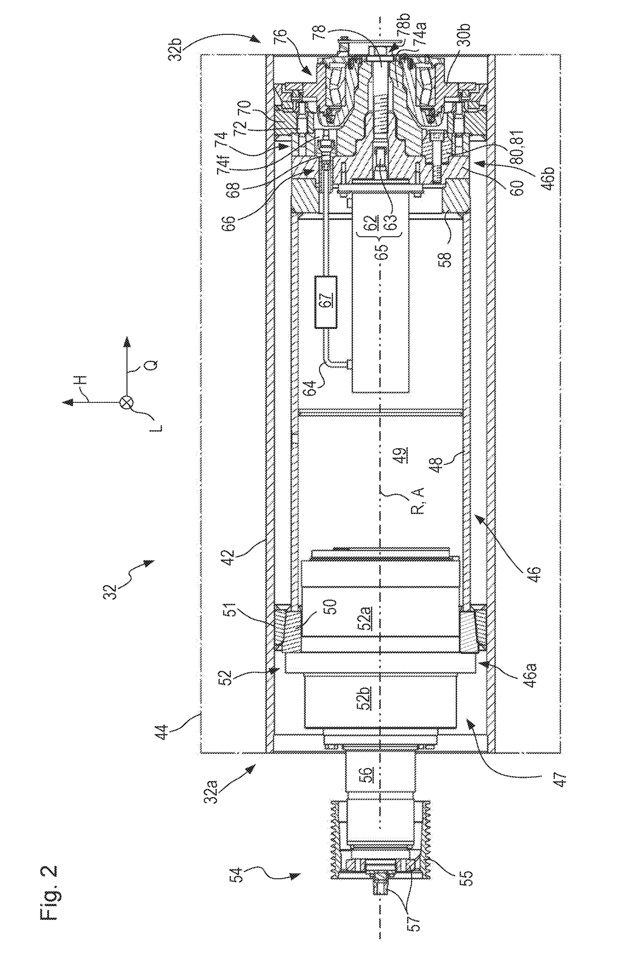
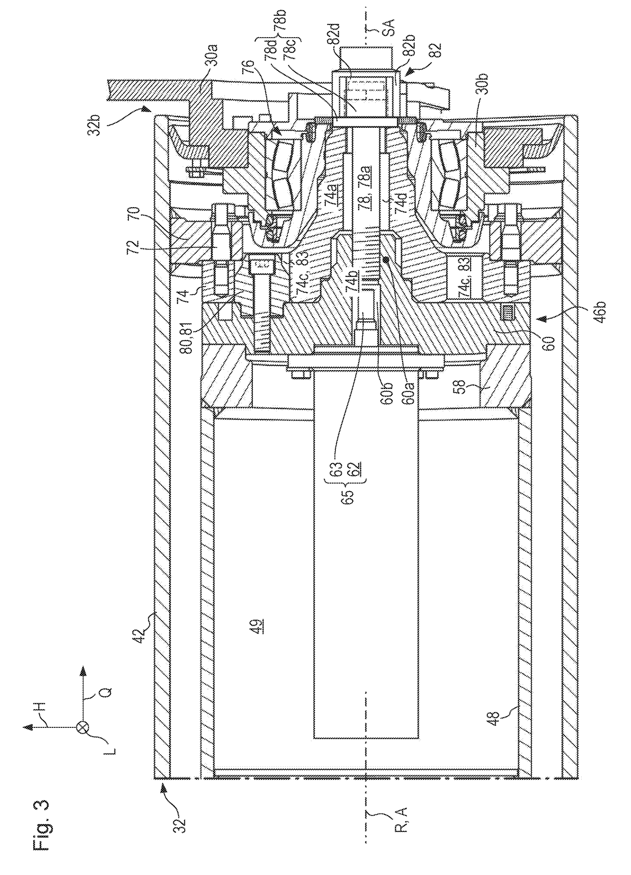
[0141]The first embodiment already explained in FIGS. 2 and 3 will be explained below in terms of operation thereof for deinstalling and installing milling drum 32 from and onto drive configuration 46 using actuator 65.
[0142]In the variant embodiment of FIGS. 4 to 6, coupling configuration 68′ is embodied directly on cover 60. Energy connector line 64 passes through coupling configuration 68′ so that hydraulic cylinder 62 can be supplied with hydraulic fluid.
[0143]The point at which energy connector line 64 connects to hydraulic cylinder 62 is selected merely by way of example. Be it noted that all the hydraulic cylinders depicted in the Figures are double-acting cylinders. Each of two hydraulic chambers, acting in opposite directions, of a hydraulic cylinder that is depicted is coupled to a respective energy connector line 64. For the sake of clarity, and because it is sufficient for a basic understanding of the embodiment, in many depictions only one of two energy connector lines ...
second embodiment
[0159]FIG. 8 shows the drive configuration and milling drum (working apparatus).
[0160]Components and component portions identical and functionally identical to those in the first embodiment are labeled in the second embodiment with the same reference characters but incremented by 100. The second embodiment of FIG. 8 is explained below only insofar as it differs from the first embodiment to an extent essential in terms of the invention.
[0161]A first essential modification of the second embodiment as compared with the previously described first embodiment is the conformation of centering stem 160a, which both acts as a centering configuration with respect to connecting flange 174 of milling drum 132 and serves as a bearing stem with respect to non-locating bearing 176.
[0162]Counterpart centering configuration 174b is thus once again embodied as a recess. In contrast to the first embodiment, in the second exemplifying embodiment centering stem 160a not only projects axially into connec...
third embodiment
[0179]Lastly, FIG. 12 depicts a third embodiment that is intended to show that central retaining bolt 278 can also be bolted to piston rod 263 of hydraulic cylinder 262 for axial positional retention of milling drum 32 on drive configuration 46.
[0180]Components and component portions identical and functionally identical to those of the first embodiment are labeled in the third embodiment with the same reference characters but incremented by 200. The third embodiment of FIG. 12 will be explained here only insofar as it differs from the first embodiment to an extent essential in terms of the invention.
[0181]The third embodiment depicted in FIG. 12, having retaining bolt 278 screwed into piston rod 263, is of course also applicable to the design of the second embodiment in which the centering stem and the bearing stem are implemented in a single component. All that is then necessary is for bolt head 278b to brace against an auxiliary component that transfers force from bolt head 278b o...
PUM
 Abstract
Description
Claims
Application Information
 - R&D
- Intellectual Property
- Life Sciences
- Materials
- Tech Scout
- Unparalleled Data Quality
- Higher Quality Content
- 60% Fewer Hallucinations
Browse by: Latest US Patents, China's latest patents, Technical Efficacy Thesaurus, Application Domain, Technology Topic, Popular Technical Reports.
© 2025 PatSnap. All rights reserved.Legal|Privacy policy|Modern Slavery Act Transparency Statement|Sitemap|About US| Contact US: help@patsnap.com


