Zoom optical system, optical apparatus and method for manufacturing the zoom optical system

a technology of optical system and zoom, applied in the field of zoom optical system, can solve the problem of insufficient optical performance of such a conventional zoom optical system

Active Publication Date: 2018-11-29
NIKON CORP
View PDF4 Cites 3 Cited by
  • Summary
  • Abstract
  • Description
  • Claims
  • Application Information

AI Technical Summary

Benefits of technology

[0009]A method for manufacturing a zoom optical system according to the present invention is a method for manufacturing a zoom optical system which comprises, in order from an object: a first lens group having positive refractive power; an intermediate group including at least one lens group and having negative refractive power as a whole; an intermediate side lens group having positive refractive power; a subsequent side lens group having positive refractive power; and a subsequent group including at lea

Problems solved by technology

Optical performance of such a conventional

Method used


Image

  • Zoom optical system, optical apparatus and method for manufacturing the zoom optical system
  • Zoom optical system, optical apparatus and method for manufacturing the zoom optical system
  • Zoom optical system, optical apparatus and method for manufacturing the zoom optical system

Examples


example 1

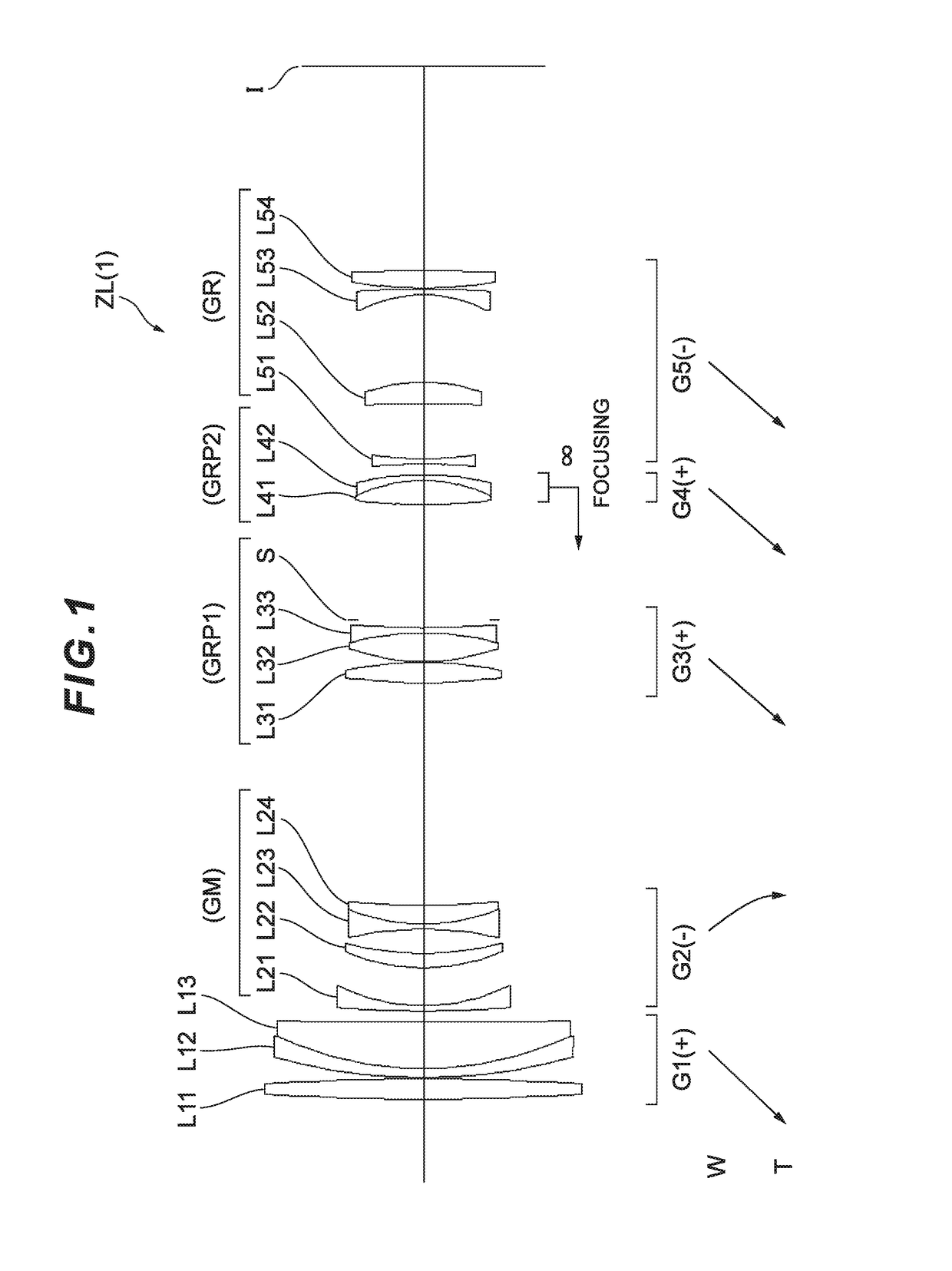
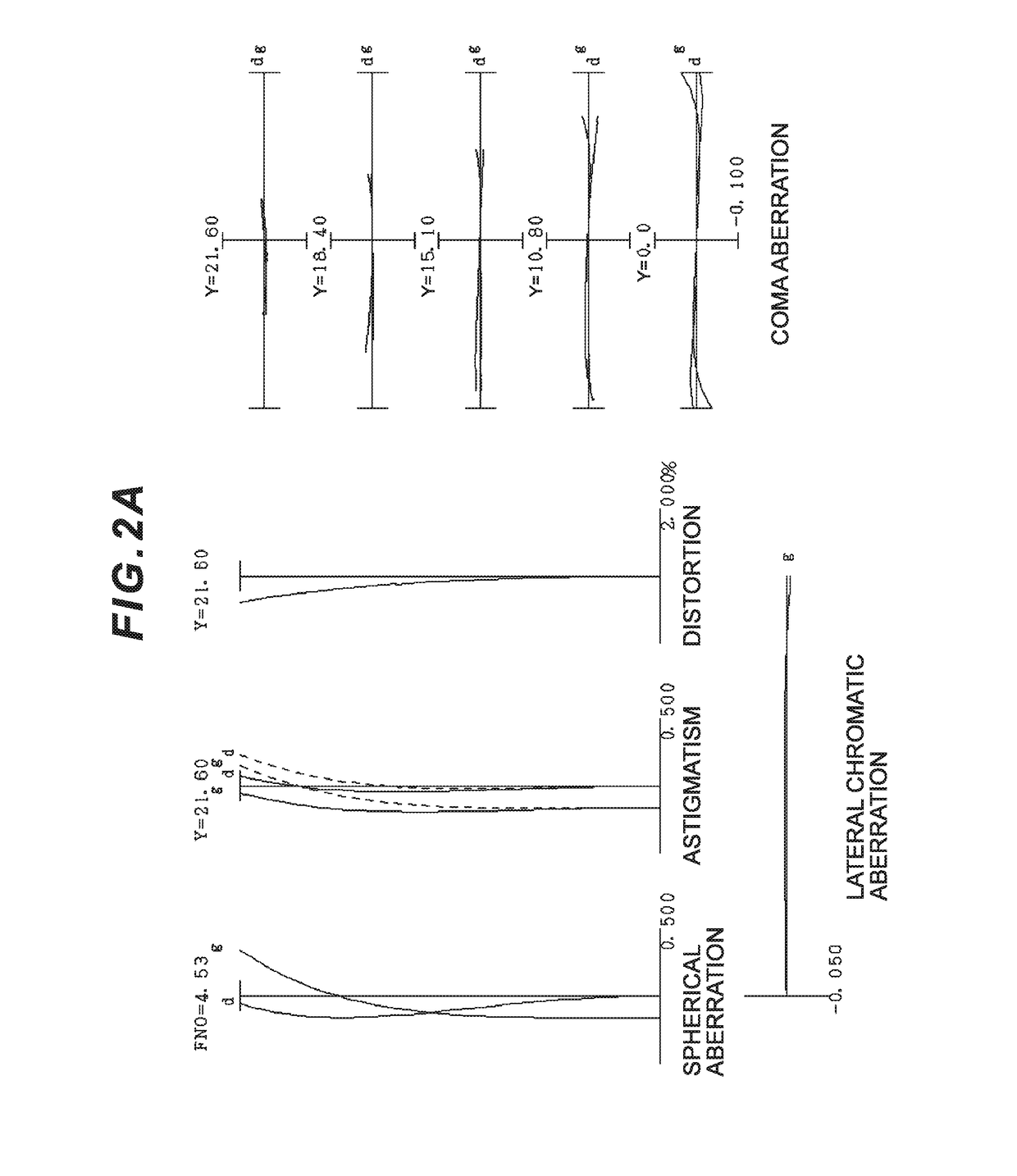
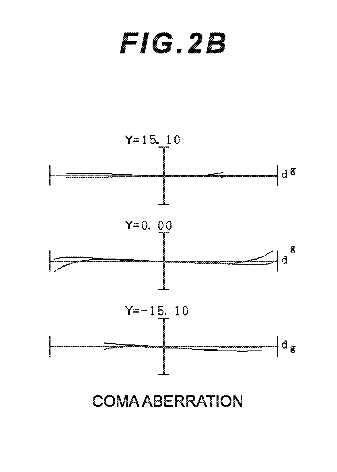
[0103]Example 1 is described with reference to FIG. 1, FIGS. 2A and 2B, FIG. 3, FIGS. 4A and 4B, and FIGS. 5A-5C and Table 1. FIG. 1 is a diagram illustrating a lens configuration of a zoom optical system according to Example 1 of the present embodiment. The zoom optical system ZL(1) according to Example 1 consists of, in order from an object: a first lens group G1 having positive refractive power; a second lens group G2 having negative refractive power; a third lens group G3 having positive refractive power; an aperture stop S; a fourth lens group G4 having positive refractive power; and a fifth lens group G5 having negative refractive power. The first to the fifth lens groups G1 to G5 each move in a direction indicated by an arrow in FIG. 1 upon zooming from a wide angle end state (W) to a telephoto end state (T). In this Example, the intermediate group GM includes the second lens group G2, the intermediate side lens group GRP1 includes the third lens group G3 and the aperture sto...

example 2

[0115]Example 2 is described with reference to FIG. 6, FIGS. 7A and 7B, FIG. 8, FIGS. 9A and 9B, and FIGS. 10A-10C and Table 2. FIG. 6 is a diagram illustrating a lens configuration of a zoom optical system according to Example 2 of the present embodiment. The zoom optical system ZL(2) according to Example 2 consists of, in order from an object: a first lens group G1 having positive refractive power; a second lens group G2 having negative refractive power; a third lens group G3 having positive refractive power; an aperture stop S; a fourth lens group G4 having positive refractive power; and a fifth lens group G5 having negative refractive power. The first to the fifth lens groups G1 to G5 each move in a direction indicated by an arrow in FIG. 6 upon zooming from a wide angle end state (W) to a telephoto end state (T). In this Example, the intermediate group GM includes the second lens group G2, the intermediate side lens group GRP1 includes the third lens group G3 and the aperture s...

example 3

[0126]Example 3 is described with reference to FIG. 11, FIGS. 12A and 12B, FIG. 13, FIGS. 14A and 14B, and FIGS. 15A-15C and Table 3. FIG. 11 is a diagram illustrating a lens configuration of a zoom optical system according to Example 3 of the present embodiment. The zoom optical system ZL(3) according to Example 3 consists of, in order from an object: a first lens group G1 having positive refractive power; a second lens group G2 having negative refractive power; a third lens group G3 having positive refractive power; an aperture stop S; a fourth lens group G4 having positive refractive power; and a fifth lens group G5 having negative refractive power. The first to the fifth lens groups G1 to G5 each move in a direction indicated by an arrow in FIG. 11 upon zooming from a wide angle end state (W) to a telephoto end state (T). In this Example, the intermediate group GM includes the second lens group G2, the intermediate side lens group GRP1 includes the third lens group G3 and the ap...


PUM


Abstract

A zoom optical system (ZL) comprises, in order from an object: a first lens group (G1) having positive refractive power; an intermediate group (GM) including at least one lens group and having negative refractive power as a whole; an intermediate side lens group (GRP1) having positive refractive power; a subsequent side lens group (GRP2) having positive refractive power; and a subsequent group (GR) including at least one lens group. The subsequent side lens group (GRP2) moves upon focusing. A following conditional expression is satisfied:
2.5<f1/fRP1<5.0
    • where,
    • f1 denotes a focal length of the first lens group (G1), and
    • fRP1 denotes a focal length of the intermediate side lens group (GRP1).

Description

TECHNICAL FIELD[0001]The present invention relates to a zoom optical system, an optical apparatus using the same and a method for manufacturing the zoom optical system.TECHNICAL BACKGROUND[0002]A zoom optical system suitable for photographic cameras, electronic still cameras, video cameras, and the like has conventionally been proposed (see, for example, Patent Document 1). Optical performance of such a conventional zoom optical system has been insufficient.PRIOR ARTS LISTPatent Document[0003]Patent Document 1: Japanese Laid-Open Patent Publication No. H4-293007 (A)SUMMARY OF THE INVENTION[0004]A zoom optical system according to the present invention comprises, in order from an object: a first lens group having positive refractive power; an intermediate group including at least one lens group and having negative refractive power as a whole; an intermediate side lens group having positive refractive power; a subsequent side lens group having positive refractive power; and a subsequen...

Claims


Application Information

Patent Timeline
IPC IPC(8): G02B15/163G02B13/02G02B13/18G02B27/64
CPCG02B15/163G02B13/02G02B13/18G02B27/646G02B15/145113G02B15/1461G02B5/005G02B9/62G02B13/009G02B15/14G02B15/20
Inventor MACHIDA, KOSUKE
Owner NIKON CORP
Why Eureka
Try Eureka