Steering assist device
a technology of assist device and steering wheel, which is applied in the direction of control device, external condition input parameters, vehicle components, etc., can solve the problems of not taking the appropriate action for this situation, another vehicle excessively approaching the own vehicle afterward, etc., and achieves the effect of improving safety
- Summary
- Abstract
- Description
- Claims
- Application Information
AI Technical Summary
Benefits of technology
Problems solved by technology
Method used
Image

Examples
example 1
of the Method for Determining of the First Half State or the Second Half State
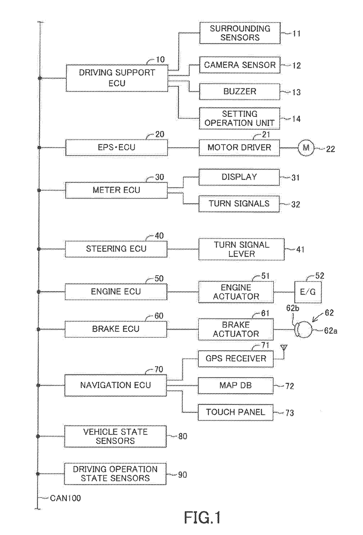
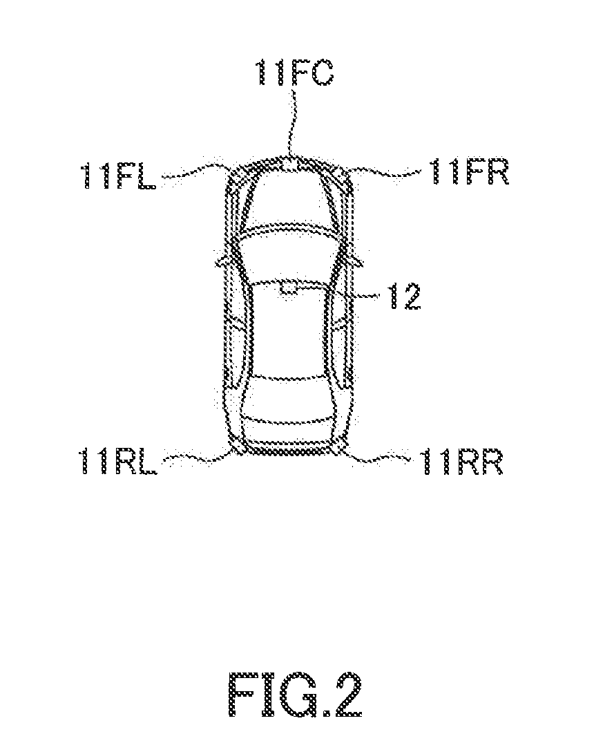
[0177]For example, when it is estimated that the entire body of the own vehicle is located within the original lane, the driving support ECU 10 determines that the progress status of the lane change is the first half state. When it is estimated that at least a part of the body of the vehicle protrudes from the original lane to the target lane, the driving support ECU 10 determines that the progress status of the lane change is the second half state. In this case, based on the lane information (in particular, the lane width and the lateral deviation Dy) detected by the camera sensor 12 and the vehicle body size (in particular, the vehicle body width), the driving support ECU 10 may determine whether or not the side surface of the own vehicle on the lane change direction side has already passed across the boundary white line which is the boundary between the original lane and the target lane to the target la...
example 2
of the Method for Determining of the First Half State or the Second Half State
[0178]As will be described later, when the approaching vehicle is detected in the first half state of the lane change, the LCA is stopped / terminated in the middle of the LCA and the steering control is performed in such a manner that the own vehicle is made to return to the center position of the original lane in the lane width direction. This steering control is referred to an “LCA cancellation control”. Even if the approaching vehicle is detected, and thus, the LCA cancellation control is performed, the own vehicle may enter the target lane, due to response delay in control, delay in the white lines recognition, recognition delay in surrounding monitoring, calculation delay, and the like. Thus, taking the overshoot due to the delay (a delay time from when the approaching vehicle is detected to when the lateral speed of the own vehicle is changed to a lateral speed in the opposite lane change direction) c...
example 3
of the Method for Determining of the First Half State or the Second Half State
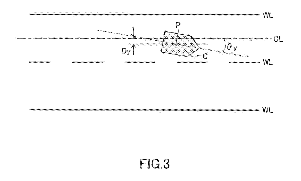
[0182]The own vehicle is likely to be prevented from entering the target lane if the LCA cancellation control is started when the lateral position of the own vehicle reaches a specific position while the LCA control is being performed. That specific position may be determined in advance and be adopted as the determination position. For example, the determination position may be set to 0.5 m (fixed value). This determination position is a position in the lane change side with respect to the lane center line CL. In this case, unless the position of the center of gravity of the own vehicle laterally moves for a distance longer than 0.5 m from the lane center line CL toward the lane change side (toward the target lane), in other words, when the lateral deviation Dy in the lane change side is 0.5 m or less, the driving support ECU 10 determines that the lane change status is the first half state. When the later...
PUM
 Abstract
Description
Claims
Application Information
 - Generate Ideas
- Intellectual Property
- Life Sciences
- Materials
- Tech Scout
- Unparalleled Data Quality
- Higher Quality Content
- 60% Fewer Hallucinations
Browse by: Latest US Patents, China's latest patents, Technical Efficacy Thesaurus, Application Domain, Technology Topic, Popular Technical Reports.
© 2025 PatSnap. All rights reserved.Legal|Privacy policy|Modern Slavery Act Transparency Statement|Sitemap|About US| Contact US: help@patsnap.com