Temperature Monitoring Systems and Methods

a technology of temperature monitoring and temperature information, applied in the field of digital cooking thermometers, can solve the problems of inconvenient user attendance, food may be overcooked, temperature loss, etc., and achieve the effect of improving the viewing of displayed temperature information

Active Publication Date: 2018-12-27
WEBER-STEPHEN PRODUCTS
View PDF0 Cites 13 Cited by
  • Summary
  • Abstract
  • Description
  • Claims
  • Application Information

AI Technical Summary

Benefits of technology

[0009]In some embodiments, the bottom surface of the base is configured to be mounted onto an angled or vertical surface. In some such embodiments, the bottom surface of the base contains at least one magnetic portion, which is configured to magnetically mount the base onto a magnetic surface. In some embodiments, the first unit is configured to engage with the base in a first orientation when the base is mounted on a substantially horizontal surface, and in a second orientation when the base is mounted on a substantially vertical surface. In such embodiments, the angled surface permits improved viewing of the displayed temperature information, which may also be improved by the orientation of the first unit.

Problems solved by technology

A drawback of standard food thermometers is that a person desiring to determine the temperature of the food is required to be physically present at the location the food is being cooked in order to view the temperature of the food displayed by the thermometer.
This inconveniently prevents the user from attending to other activities and / or requires the user to return to the cooking location to monitor the progress of the cooking.
If the user does not return in time, the food may be overcooked.
Moreover, if a grill or oven is being employed to cook the food, opening the grill or oven is required to measure the temperature, which may result in temperature loss and / or inconsistent temperature cooking.

Method used


Image

  • Temperature Monitoring Systems and Methods
  • Temperature Monitoring Systems and Methods
  • Temperature Monitoring Systems and Methods

Examples


Embodiment Construction

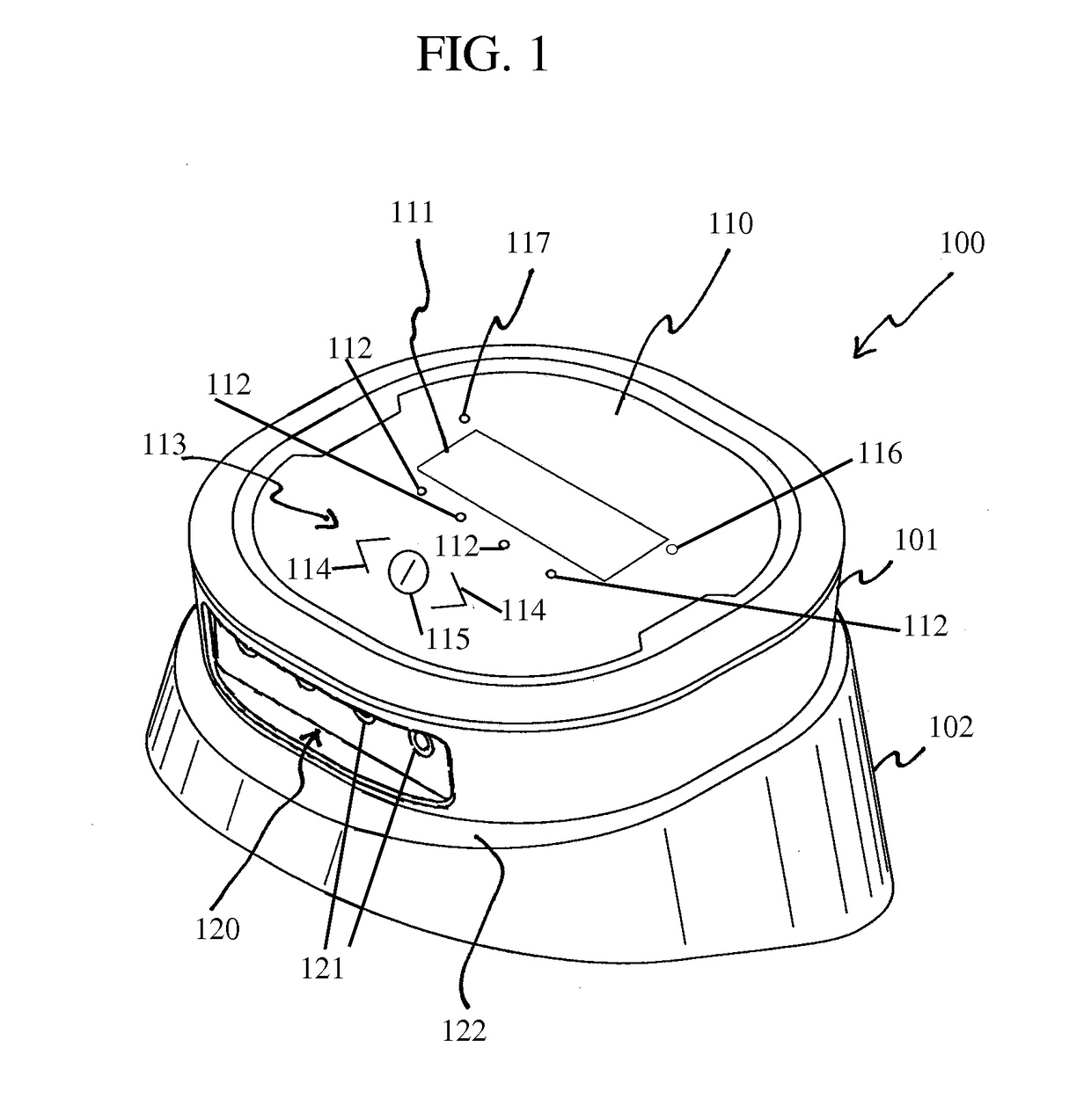
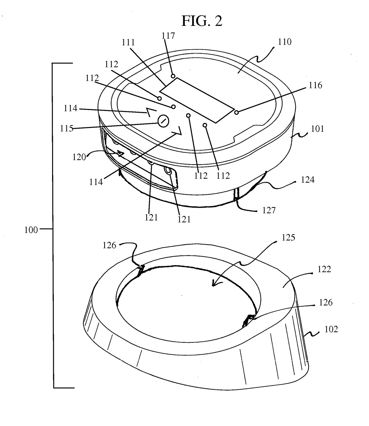
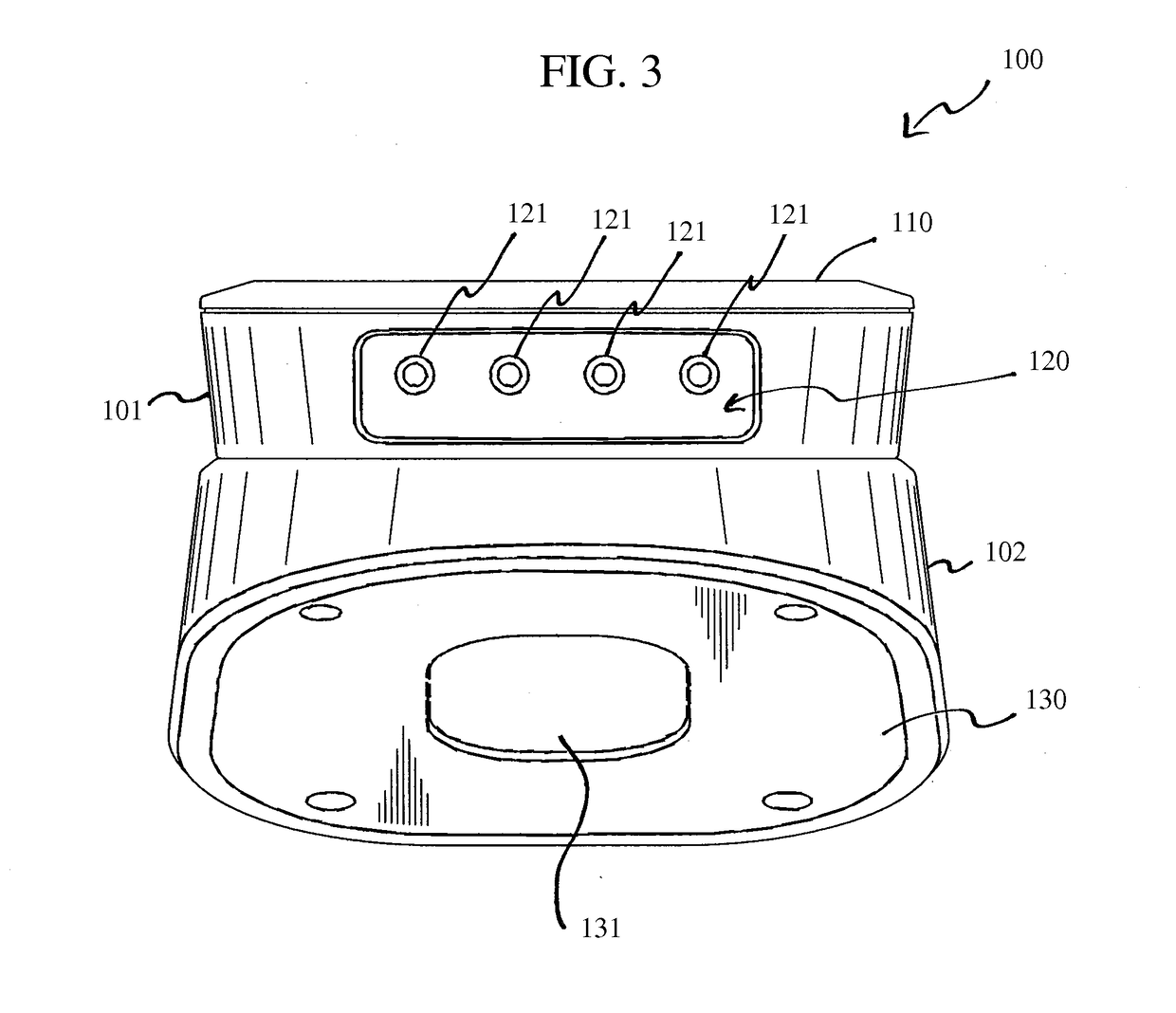
[0035]The present invention provides temperature monitoring systems and methods whereby the temperature status of an item or items may be monitored and / or controlled from a location that is different from the location of the item(s). In various embodiments, the temperature status may be monitored and / or controlled via communication between a first device located at or near the location at which the item is located, and a second device located at a different location. The first device may include or be operatively connected to one or more temperature sensors or probes by which the temperature(s) of the item(s) is determined and communicated to the first device. Temperature information is then transmitted to the second device, which is relayed to a user by visual or other indication.

[0036]The heating parameters of the item may be entered, programmed, or selected by a user using the second device. The second device may then determine various heating characteristics of the item, such as...


PUM

PropertyMeasurementUnit
viewing angleaaaaaaaaaa
temperatureaaaaaaaaaa
thermal probeaaaaaaaaaa

Abstract

A temperature monitoring system for monitoring a temperature status of an item from a location different than a location at which the item is located is disclosed. The temperature monitoring system includes a base having a top surface and a bottom surface, and a first unit removably engageable with the top surface of the base in at least a first orientation and a second orientation. The first unit is configured to monitor a measured temperature, to display information regarding the measured temperature, and / or to transmit temperature information to a user device. The temperature monitoring system may also include at least one thermal or temperature probe configured to measure the temperature of the item, including a probe tip, probe wire, and probe plug. The temperature monitoring system may also include one or more probe supports configured to releasably attach to the base and configured to releasably retain a thermal probe thereon.

Description

CROSS-REFERENCE TO RELATED APPLICATIONS[0001]This application claims benefit under 35 U.S.C. § 119(e) to U.S. Provisional Patent Application Nos. 62 / 075,217 and 62 / 075,219, filed Nov. 4, 2014, which are incorporated herein by reference in its entirety.FIELD OF THE INVENTION[0002]The present invention relates to temperature monitoring systems and methods, such as for food preparation. Particularly, the present invention relates to digital cooking thermometers.BACKGROUND INFORMATION[0003]In many heating processes such as food preparation and cooking, the temperature of the item or material being heated is of critical importance in obtaining a suitable or desired result. In cooking, for example, the temperature of the food plays a role, often determinative, in the degree to which the food is cooked. The temperature itself may be indicative as to a degree to which the food is cooked. The degree to which the food is cooked is not only relevant to the taste of the food, as may be desired ...

Claims


Application Information

Patent Timeline
Patent Type & Authority Applications(United States)
IPC IPC(8): G01K13/00G01K1/14G01K1/02
CPCG01K1/028G01K1/143G01K2207/06G01K1/024G01K13/00G01K1/14
Inventor ALLEN, SR., CHRISTOPHER J.
Owner WEBER-STEPHEN PRODUCTS
Why Eureka
Try Eureka