Robotic gripper

a robot and gripper technology, applied in the field of robotic tools, can solve the problems of wear and tear of moving parts, and the components of various robotic tools require frequent replacement and adjustmen

Active Publication Date: 2019-01-31
CONTROL & POWER SYST
View PDF3 Cites 19 Cited by
  • Summary
  • Abstract
  • Description
  • Claims
  • Application Information

AI Technical Summary

Problems solved by technology

As with any machine or tool, moving parts are subject to wear and, therefore, the components of various robotic tools require frequent replacement and adjustment.

Method used


Image

  • Robotic gripper
  • Robotic gripper
  • Robotic gripper

Examples


Embodiment Construction

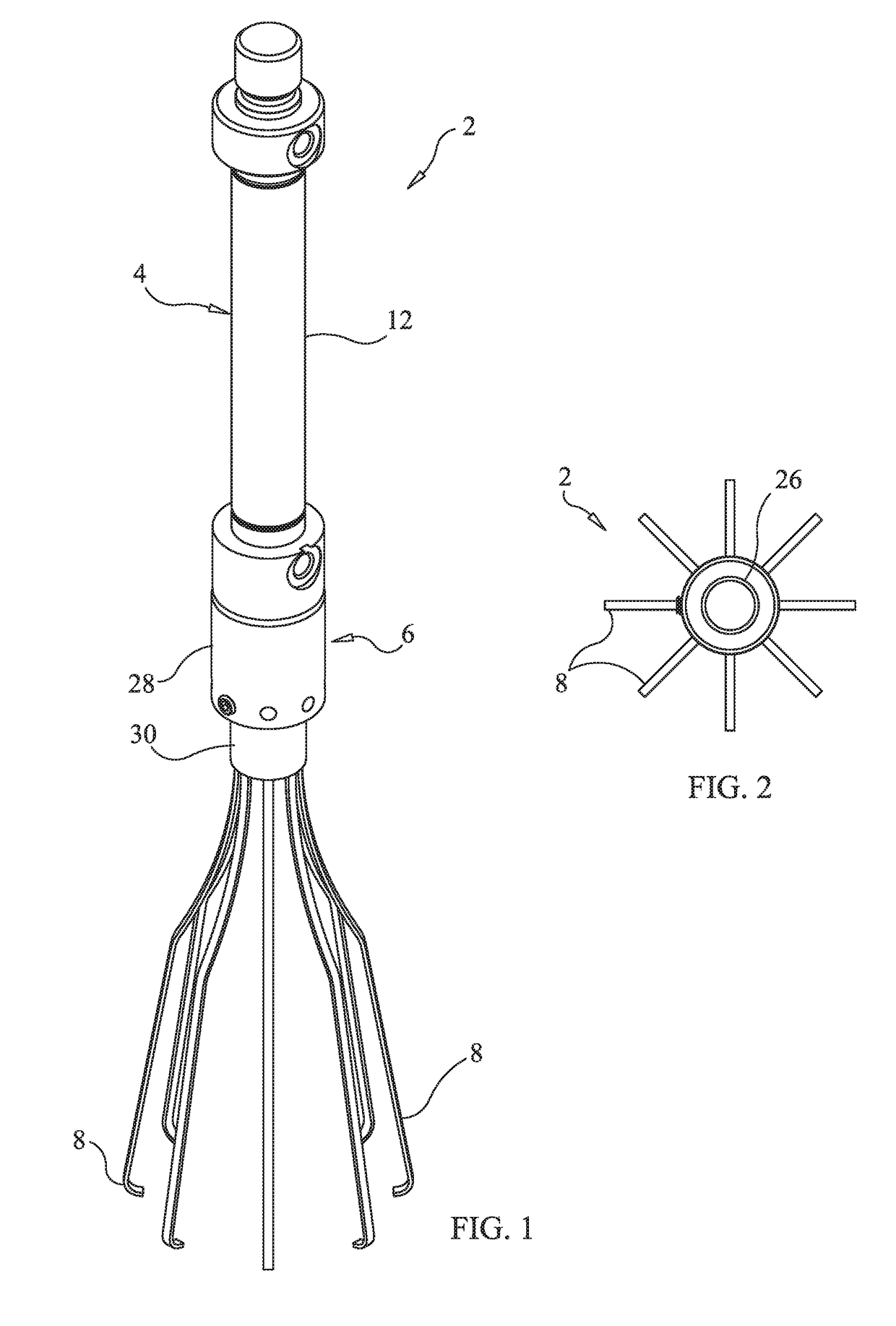
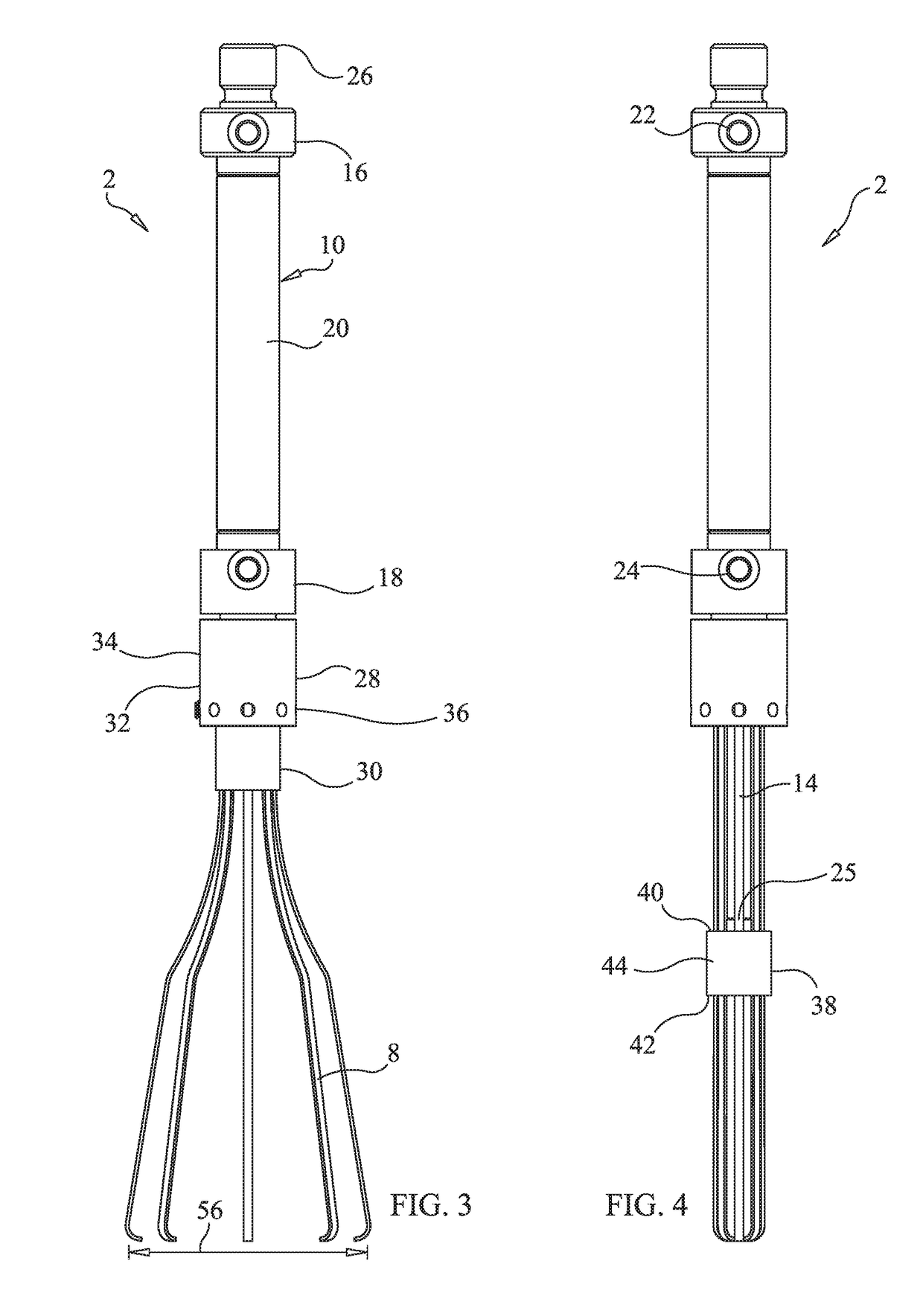
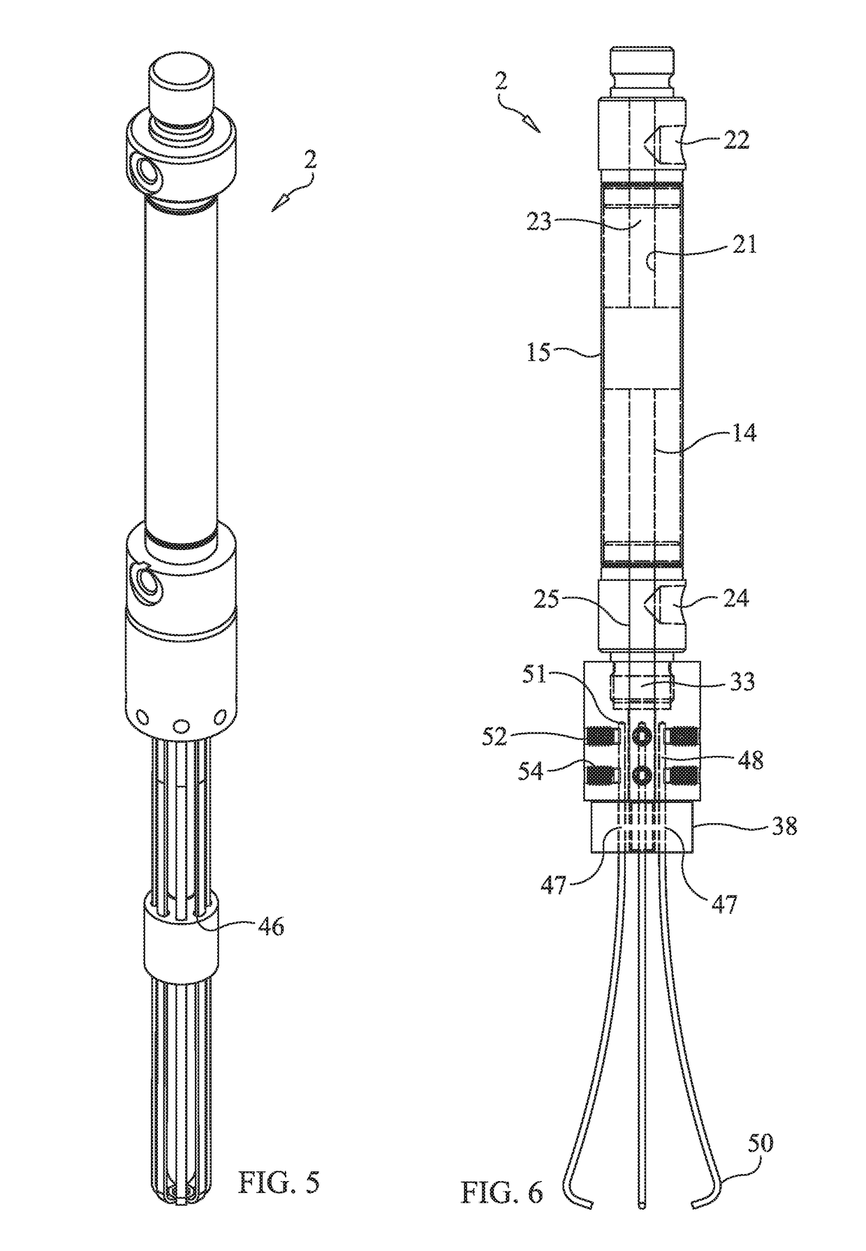
[0016]Reference should initially be made to FIG. 1 of the drawings, where it can be seen that a robotic gripper 2 for grasping target objects (e.g., components or materials) formed in accordance with the present invention includes a linear actuator 4 and a gripping assembly 6 mechanically coupled thereto. The gripping assembly 6 preferably includes a plurality (preferably, eight) of resilient wire fingers 8. The resilient fingers 8 are selectively adjustable between a closed position, as shown in FIGS. 4 and 5 of the drawings, and an open position, as shown in FIGS. 1, 2, 3 and 6 of the drawings, to grasp and release the target object, respectively. As will be described in greater detail in the forthcoming paragraphs, a robotic system (not shown) mechanically engages the robotic gripper 2 to maneuver and operate the gripper 2 and manipulate target objects.

[0017]In a preferred embodiment of the present invention, the linear actuator 4 is configured as a pneumatic cylinder 10 that com...


PUM


Abstract

A robotic gripper for grasping a target object includes a linear actuator and a gripping assembly. The gripping assembly is coupled to the linear actuator and includes a plurality of fingers that are positioned to selectively grasp and release the target object. The linear actuator includes an air cylinder and a linearly movable rod that reciprocates within the air cylinder between a retracted position and an extended position. The gripping assembly includes a finger holder and a finger closer. The fingers are affixed to the finger holder and extend from the finger holder through openings formed in the finger closer. The finger closer is coupled to the linearly movable rod which reciprocatingly drives the finger closer over the fingers to adjust the fingers between a first position in which the fingers grasp the target object and a second position in which the fingers release the target object.

Description

CROSS-REFERENCE TO RELATED APPLICATIONS[0001]This application is related to U.S. Provisional Patent Application Ser. No. 62 / 537,537, filed on Jul. 27, 2017, and entitled “Robotic Gripper”, the disclosure of which is hereby incorporated by reference and on which priority is hereby claimed.BACKGROUND OF THE INVENTIONField of the Invention[0002]The present invention generally relates to robotic tools, and more particularly relates to robotically operated gripping tools.Description of the Prior Art[0003]Product manufacturing is often implemented by automated assembly lines that incorporate robotics and conveyor belt systems. Multi-axis robots, such as ADEPT™ and SCARA™ type robotic platforms, interact with conveyor belt systems to assemble products from a variety of supplied components. Robotic systems typically include at least one working arm that is engageable with a plurality of assembly tools, some of which may be pneumatically operated. For example, screwdrivers and product manipu...

Claims


Application Information

Patent Timeline
Patent Type & Authority Applications(United States)
IPC IPC(8): B25J9/14B25J9/00B25J15/00B25J15/10B25J15/02
CPCB25J15/12B25J9/144B25J15/10B25J15/024B25J9/0027
Inventor AZAZI, BRYANEZZO, CARMIN K.
Owner CONTROL & POWER SYST
Why Eureka
Try Eureka