Slow area massage water outlet device

a massage water and slow technology, applied in the direction of spray nozzles, spray nozzles, spray nozzles, etc., can solve the problems of difficult feeling, poor massage sensation of the massage water, and the modern showerhead no longer satisfied with the function of a single water outlet, so as to achieve a strong massage sensation and slow switching frequency of the massage water

Active Publication Date: 2019-02-07
XIAMEN SOLEX HIGH TECH IND CO LTD
View PDF3 Cites 8 Cited by
  • Summary
  • Abstract
  • Description
  • Claims
  • Application Information

AI Technical Summary

Benefits of technology

[0003]The main technical problem to be solved by the present invention is to provide a slow area massage water outlet devic...

Problems solved by technology

Therefore, the modern showerhead is no longer satisfied with a single water outlet function, but various functions are realized by changing the shape of the water spray, the water outlet area, the intensity of the water outlet, and the like.
The ...

Method used


Image

  • Slow area massage water outlet device
  • Slow area massage water outlet device
  • Slow area massage water outlet device

Examples


embodiment 1

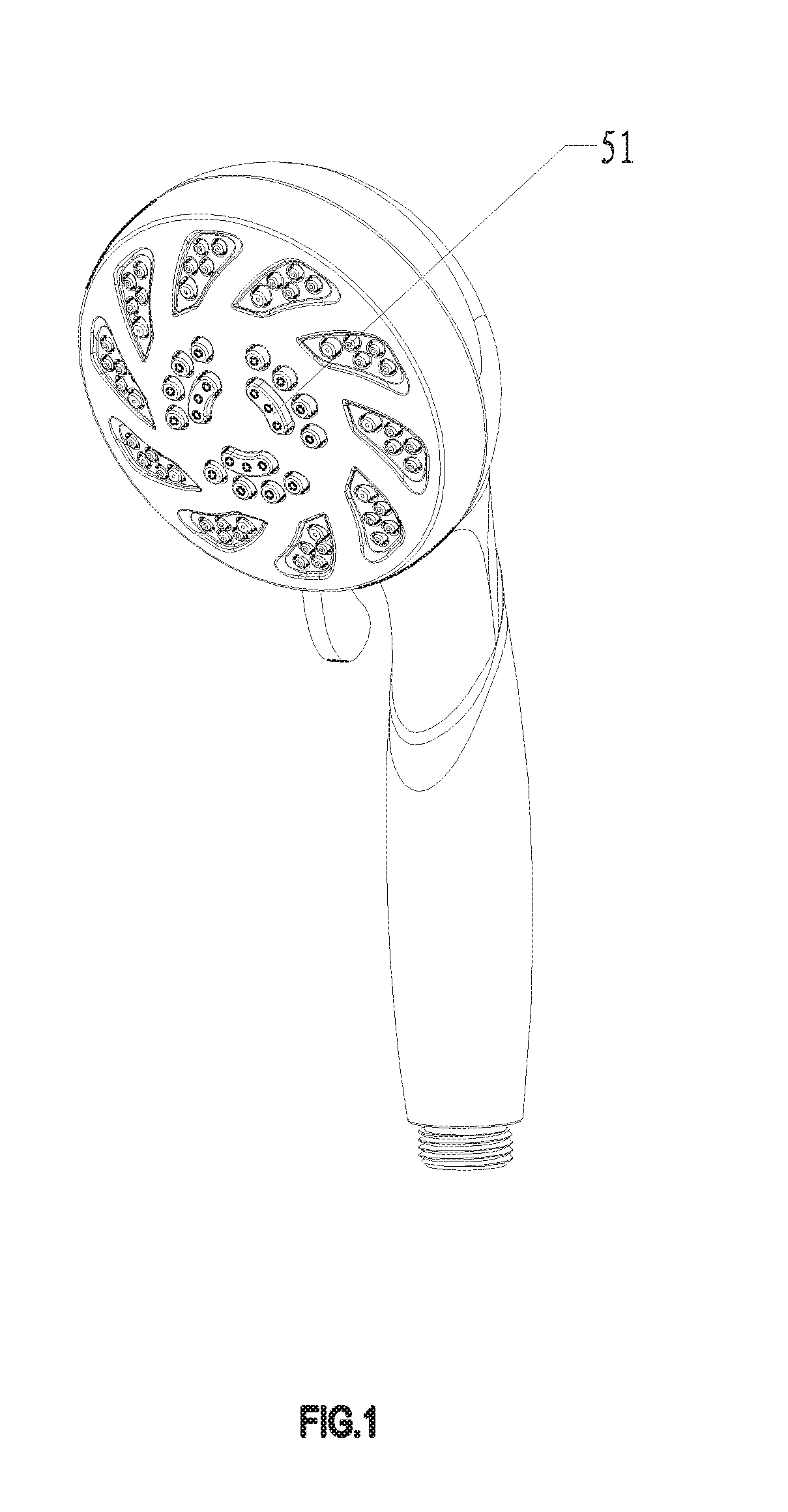
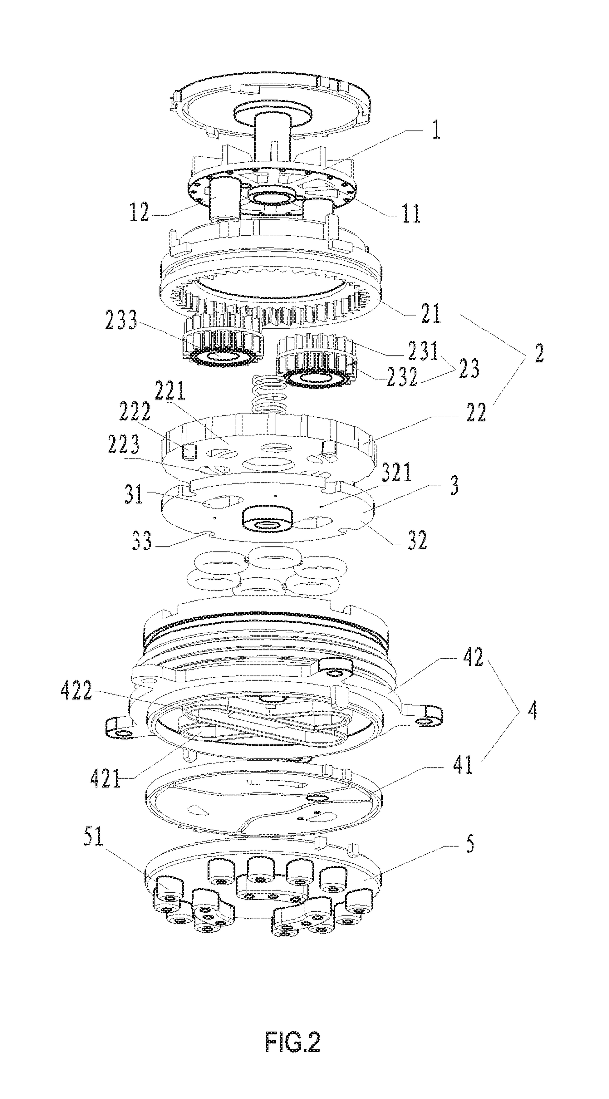
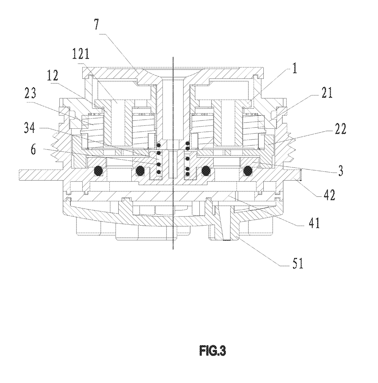
[0067]Referring to FIG. 1-11, a slow area massage water outlet device, in this embodiment, is a showerhead, may also be other outlet devices. The shower includes a water flow driving member 1, a speed reducing member 2, a linking member 3, a water dividing member 4 and a water outlet member 5;

[0068]the speed reducing member 2 is respectively drivably connected with the water flow driving member 1 and the linking member 3, and the water flow driving member 1 drives the linking member 3 to move by the speed reducing member 2;

[0069]the water diversion member 4 has at least two separately isolated water diversion cavities; one end of the water diversion cavity is a water inlet end and the other end is a water outlet end; the water outlet end of each water diversion cavity is respectively communicated with the water outlet hole 51 in different regions of the water outlet member 5; the linking member 3 has a water inlet 31 and a water sealing surface 32;

[0070]during the movement of the li...

embodiment 2

[0086]Referring to FIG. 12-15, the difference between this embodiment and embodiment 1 lies in that: the number of the water diversion cavity is two, the water outlet of the water outlet member 5 is circularly arranged, and is divided into two annularly disposed concentric circles water outlet area. Each ring-shaped water outlet area respectively corresponds to a water diversion cavity. When the linking member 3 moves, the two ring-shaped water outlet areas form a massage water outlet effect that periodically alternately discharging water. The rest is the same as that in embodiment 1, and will not be repeated here.

embodiment 3

[0087]Referring to FIG. 16-19, the difference between this embodiment and embodiment 1 lies in that: the water diversion cavity is two, and the water outlet holes 51 of the water outlet member 5 are arranged in an array. When the linking member 3 moves, the water outlet holes 51 in each row are divided into two areas according to the odd and even numbers to alternately discharge the water; and the water outlet holes of the upper row and the lower row of the simultaneous discharge are staggered.


PUM


Abstract

A slow area massage water outlet device has an impeller, a planetary gear speed reduction mechanism, a rotating water blocking plate, a water diversion member and a water outlet member; the planetary gear speed reduction mechanism is respectively communicated with the impeller and the rotating water blocking plate; the impeller is rotated by a planetary gear decelerating mechanism to rotate the water blocking plate; the water diversion member has at least two separately isolated water diversion cavities; one end of the water diversion cavity is a water inlet end and the other end is a water outlet end; the water outlet end of each of the water diversion cavities is respectively communicated with the water outlet holes of different areas in the water outlet member; the rotating water blocking plate has a water outlet and a water sealing surface.

Description

FIELD OF INVENTION[0001]The present invention relates to a water outlet device, and more particularly to a massage water outlet device.BACKGROUND OF INVENTION[0002]Existing massage water upgrade, the existing massage water are arranged in the same circle, plugging are very few, and the frequency is very fast, massage is not strong, therefore, planning a area slow water outlet, the tap is changed to more areas, the water outlet way is changed to sub-regional intermittent water outlet. With the accelerated pace of people's lives, the shower is no longer just a means of cleaning the body, but also a way to relieve fatigue decompression. Therefore, the modern showerhead is no longer satisfied with a single water outlet function, but various functions are realized by changing the shape of the water spray, the water outlet area, the intensity of the water outlet, and the like. One of the most important point is massage water. The traditional shower use intermittent water to achieve massag...

Claims


Application Information

Patent Timeline
IPC IPC(8): B05B3/04B05B1/16B05B1/18
CPCB05B3/04B05B1/1645B05B1/18A61H9/00B05B1/083B05B1/1636B05B12/04
Inventor LIN, FENGDEZHANG, MINGFUWANG, TIANMINGCHEN, WENXING
Owner XIAMEN SOLEX HIGH TECH IND CO LTD
Why Eureka
Try Eureka