
Fuel Assembly and Reactor Loaded with the Same

a fuel assembly and assembly technology, applied in nuclear reactors, nuclear elements, greenhouse gas reduction, etc., can solve the problems of reducing reducing the neutron absorption effect of burnable poison, and increasing the amount of plutonium loading, so as to increase the average fissile plutonium enrichment of a mox fuel and flatten the excess reactivity

Active Publication Date: 2019-02-14
HITACHI LTD
View PDF2 Cites 0 Cited by
  • Summary
  • Abstract
  • Description
  • Claims
  • Application Information

AI Technical Summary

Benefits of technology

The present invention provides a fuel assembly and a reactor that can increase the average fissile plutonium enrichment of a MOX fuel while linearizing the change of the infinite multiplication factor of fuel and flattening excess reactivity. This helps to improve the performance of the reactor.

Problems solved by technology

However, since the average energy of neutrons becomes high in the reactor using the MOX fuel (the neutron energy spectrum becomes hard), the neutron absorption effect of the burnable poison becomes small.
Further, since plutonium is taken out by reprocessing, a concentration process to increase the plutonium enrichment is unnecessary, unlike the uranium fuel.
However, the amount of loading of plutonium is decreased if the burnable poison is added to and loaded in the uranium fuel rod, which hinders the increase in the enrichment.
However, since the neutron moderation effect is large on the outermost periphery and the neutron energy spectrum becomes soft, the burnable poison is burned out at an early stage.
The addition amount of the burnable poison has an upper limit due to problems such as fuel manufacturability and a decrease in thermal conductivity at loading.

Method used


Image

  • Fuel Assembly and Reactor Loaded with the Same
  • Fuel Assembly and Reactor Loaded with the Same
  • Fuel Assembly and Reactor Loaded with the Same

Examples


first embodiment

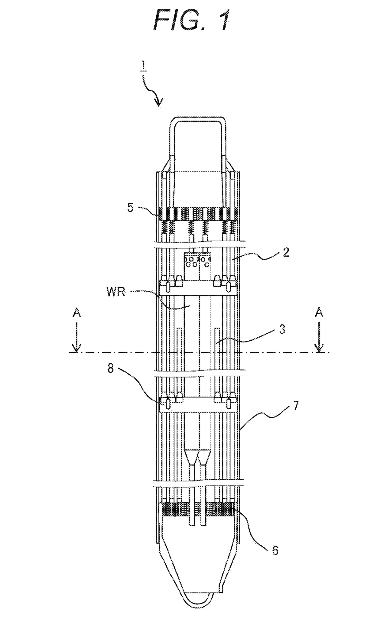
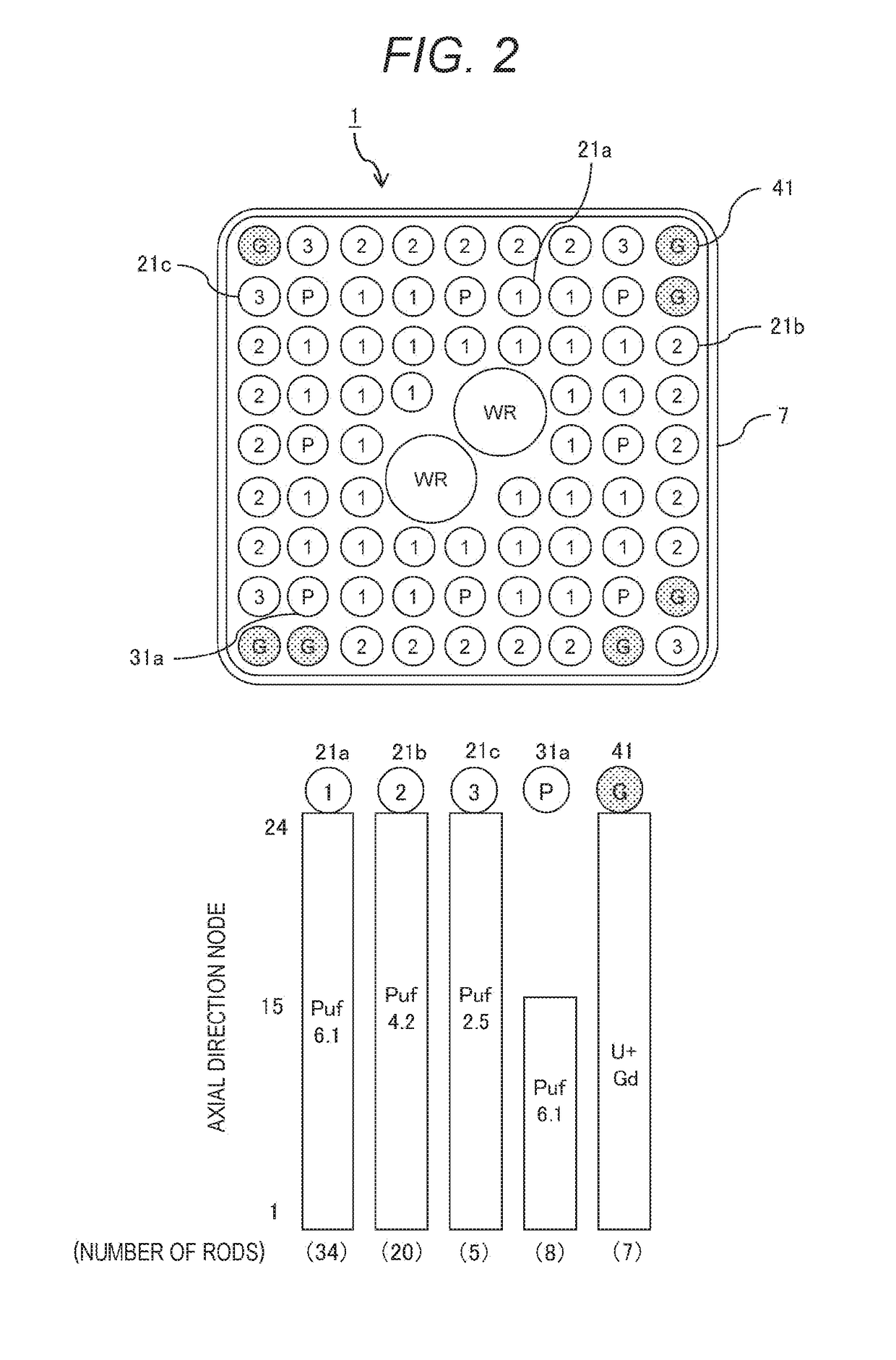
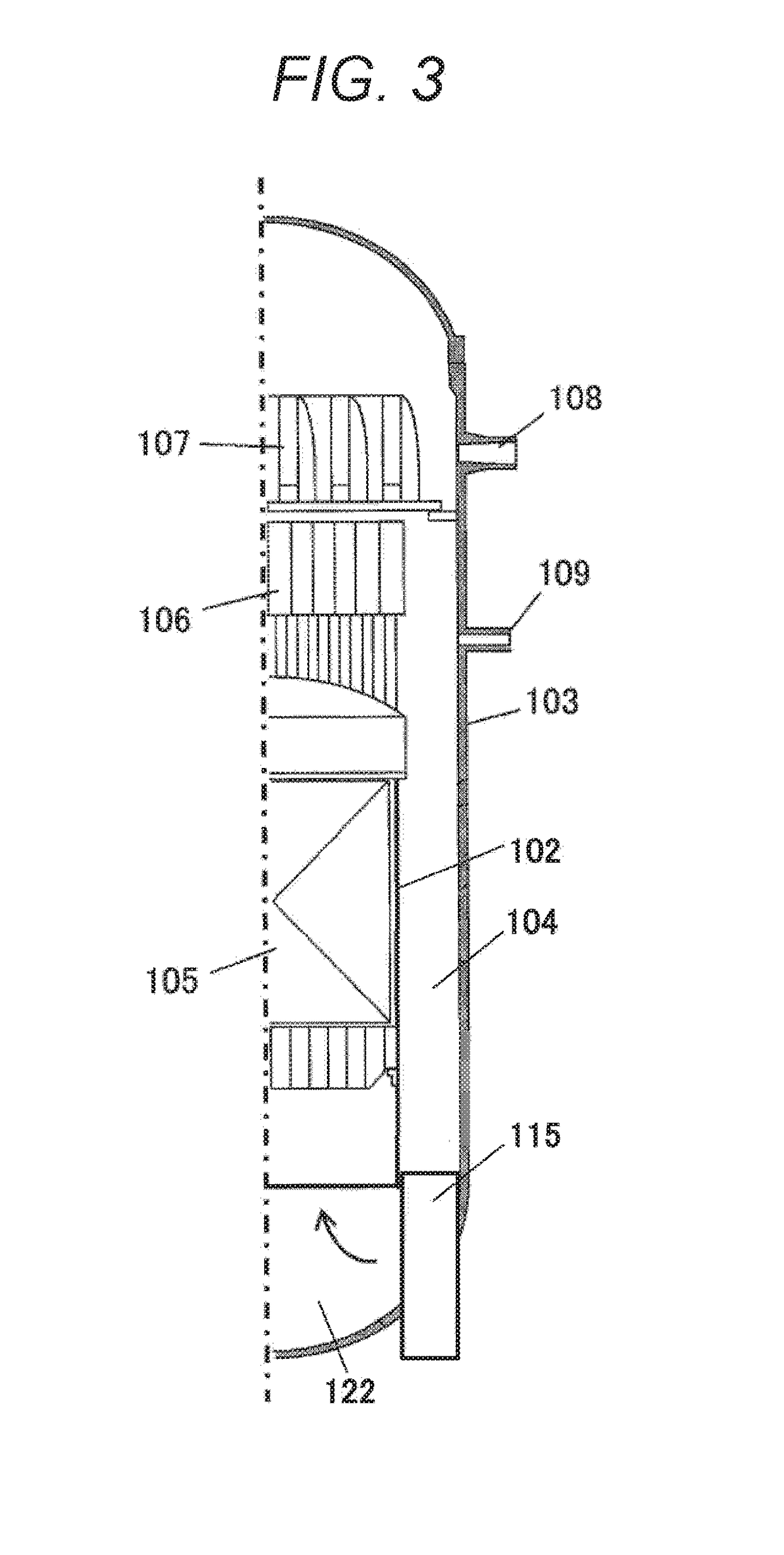
[0035]FIG. 1 is an overall schematic configuration view of a fuel assembly of a first embodiment according to an embodiment of the present invention, FIG. 2 is a sectional view taken along line AA (horizontal sectional view) of the fuel assembly illustrated in FIG. 1, and is a view illustrating the enrichment of each fuel rod and addition of burnable poison, and FIG. 3 is a schematic configuration view of an advanced boiling water reactor provided with a reactor loaded with the fuel assembly illustrated in FIG. 2.

[0036]As illustrated in FIG. 3, in the advanced boiling water reactor (ABWR), a cylindrical reactor shroud 102 is provided in a reactor pressure vessel (reactor vessel) 103, and a reactor 105 loaded with a plurality of fuel assemblies (not illustrated) is disposed in the reactor shroud 102. Further, a steam-water separator 106 extending upward of the reactor 105 and a steam dryer 107 arranged above the steam-water separator 106 are provided in the reactor pressure vessel (h...

second embodiment

[0046]FIG. 4 is a horizontal sectional view of a fuel assembly of a second embodiment according to another embodiment of the present invention, and is a view illustrating the enrichment of each fuel rod and addition of burnable poison. In the present embodiment, the fissile plutonium enrichment in fuel rods and arrangement positions of gadolinium-containing fuel rods, which are burnable poison-containing fuels, are different from those in the first embodiment. The other points are similar to those of the first embodiment, and hereinafter description overlapping with the first embodiment will be omitted.

[0047]As illustrated in the upper view of FIG. 4, fuel rods 22a to 22d, a partial length fuel rod 32a, a partial length fuel rod 32b, a water rod WR, and a gadolinium-containing fuel rod 42 that is a fuel rod containing gadolinium that is burnable poison are arranged in a nine-row by nine-column square lattice formed in a channel box 7 in a horizontal section of a fuel assembly 1a in ...

third embodiment

[0051]FIG. 5 is a horizontal sectional view of a fuel assembly of a third embodiment according to another embodiment of the present invention, and is a view illustrating the enrichment of each fuel rod and addition of burnable poison. In the present embodiment, the fissile plutonium enrichment in fuel rods and arrangement positions of gadolinium-containing fuel rods, which are burnable poison-containing fuels, are different from those in the first embodiment. The other points are similar to those of the first embodiment, and hereinafter description overlapping with the first embodiment will be omitted.

[0052]As illustrated in the upper view of FIG. 5, fuel rods 23a to 23c, partial length fuel rods 33a to 33c, a water rod WR, and a gadolinium-containing fuel rod 43 that is a fuel rod containing gadolinium that is burnable poison are arranged in a nine-row by nine-column square lattice formed in a channel box 7 in a horizontal section of a fuel assembly 1b in the fuel assembly 1b of th...


PUM


Abstract

A fuel assembly capable of linearizing change of an infinite multiplication factor of a fuel and flattening excess reactivity while increasing average fissile plutonium enrichment of a MOX fuel, and a reactor loaded with the fuel assembly can be provided. A fuel assembly includes first fuel rods containing Pu and not containing burnable poison, a second fuel rod containing uranium and burnable poison and not containing Pu, a water rod, and a channel box accommodating the first and second fuel rods and the water rod in a bundle. The second fuel rod is disposed on an outermost periphery and / or adjacent to the water rod, of a fuel rod array in a horizontal section, N2<N1 (N2 is a positive integer including zero) is satisfied where the number of the second fuel rods arranged on the outermost periphery is N1 and the number of the second fuel rods arranged adjacent to the water rod is N2, and W2<N2+W0<W1 (W2 is a positive integer including zero) is satisfied where the number of the second fuel rods arranged without being vertically and / or horizontally adjacent to each other in the horizontal section is W0, the number of the second fuel rods arranged vertically and / or horizontally adjacent to only one second fuel rod in the horizontal section is W1, and the number of the second fuel rods arranged vertically and / or horizontally adjacent to two second fuel rods in the horizontal section is W2, of the second fuel rods arranged on the outermost periphery.

Description

TECHNICAL FIELD[0001]The present invention relates to a fuel assembly and a reactor loaded with the fuel assembly, and more particularly to a fuel assembly suitable for application to a boiling water reactor, and a reactor loaded with the fuel assembly.BACKGROUND ART[0002]A plurality of fuel assemblies is loaded in a reactor of a boiling water reactor. The fuel assembly includes a plurality of fuel rods enclosing a plurality of fuel pellets including a nuclear fuel material (for example, uranium oxide), an upper tie plate that supports upper end portions of the fuel rods, a lower tie plate that supports lower end portions of the fuel rods, a plurality of fuel spacers that holds spacing between the fuel rods, and a square tubular channel box. The channel box has an upper end portion attached to the upper tie plate and extends toward the lower tie plate, and surrounds the plurality of fuel rods bundled by the plurality of fuel spacers.[0003]A plurality of control rods is inserted in t...

Claims


Application Information

Patent Timeline
IPC IPC(8): G21C3/328G21C3/62G21C3/322
CPCG21C3/328G21C3/62G21C3/322G21C1/084G21Y2002/10G21Y2004/10G21C3/326G21C3/623G21C7/04Y02E30/30G21C3/3225
Inventor MITSUYASU, TAKESHIAOYAMA, MOTOO
Owner HITACHI LTD
Learn More