Deployable and smart car bumper

Active Publication Date: 2019-02-21
OMNITEK PARTNERS LLC
View PDF11 Cites 3 Cited by
  • Summary
  • Abstract
  • Description
  • Claims
  • Application Information

AI Technical Summary

Benefits of technology

[0009]Many current vehicles already have sensory devices for detecting objects in front, back and sometimes on the side of the vehicle and alert the driver or automatically take appropriate evasive or braking actions. Such sensors are mostly based on Radio Frequency (RF), Radar, or optical (laser) or camera or a combination of thereof. Such sensors that can detect object in collision course with the vehicle in front and rear as well as the sides of a vehicle are well known in the art. It is also expected that most vehicles will be equipped with such sensors in t

Problems solved by technology

To achieve this objective, many of the known bumper systems have been developed—but with undesirably large protruding sections and appearance that has prevented their consumer acceptance.
This arrangement of a simple beam-like structure, however, provides an inefficient energy absorbing system and hence the bumper syste

Method used


Image

  • Deployable and smart car bumper
  • Deployable and smart car bumper
  • Deployable and smart car bumper

Examples


first embodiment

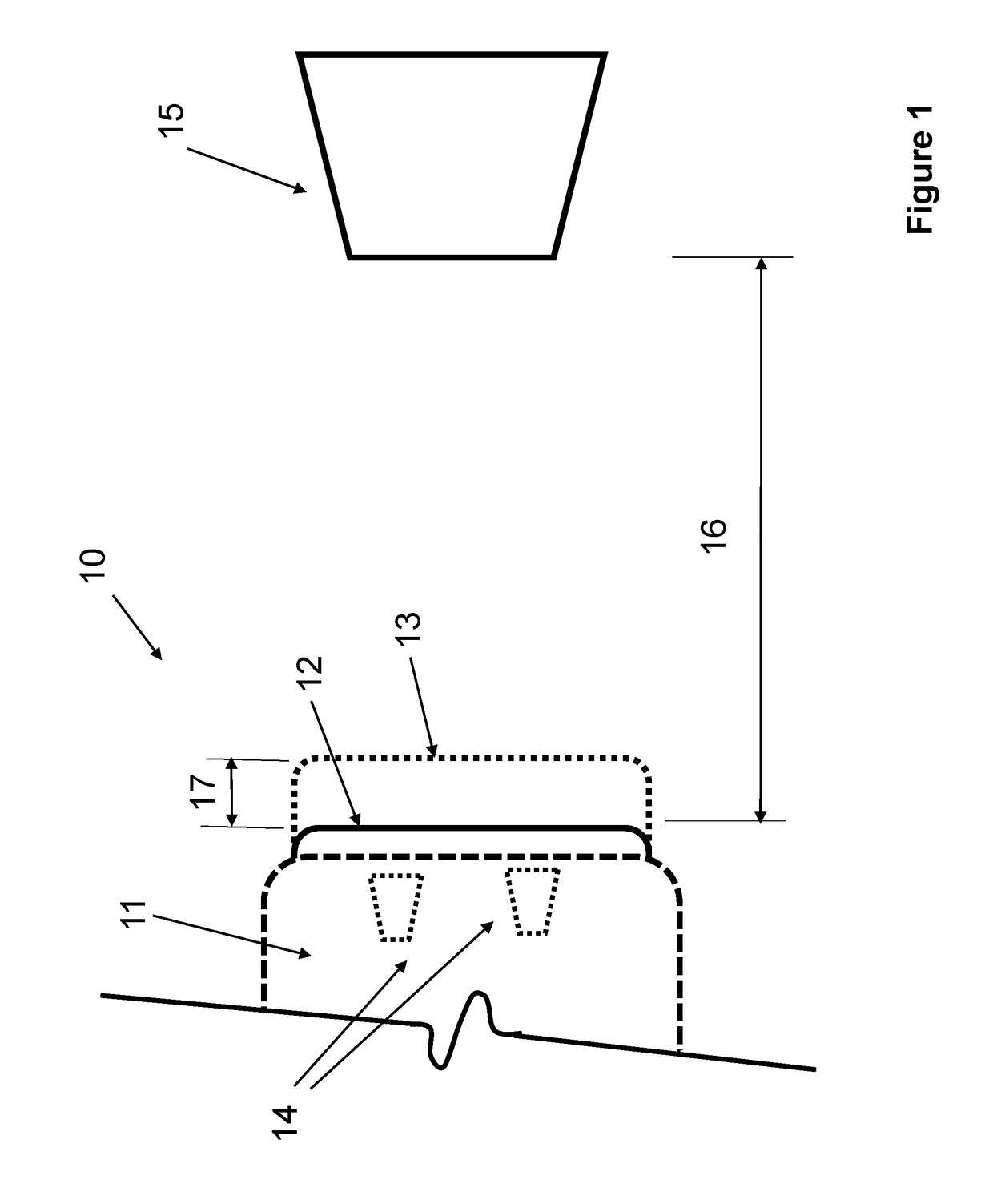
[0025]A schematic of the first embodiment is shown in FIG. 1. In FIG. 1, the frontal (or rear) section 11 of a vehicle is shown which is equipped with the deployable bumper 12, shown in its pre-deployment configuration with solid lines. The vehicle is considered to be equipped with a sensory system (not shown but consisting of appropriate electronics depending on the type of sensor being used and can be equipped with one or more microprocessor to perform velocity and acceleration and other related calculations) with at least one sensor 14, which can detect the distance between the (un-deployed) bumper 12 and any stationary or moving object 15 in the path of motion of the bumper. Then when the sensors 14 of the sensory system detects the object 15 and it is at a relative distance 16 between the bumper 12 and the facing surface of the object 15, and after determining the relative velocity and acceleration, i.e., the rate with which the distance 16 is decreasing (relative velocity) and...

embodiment 20

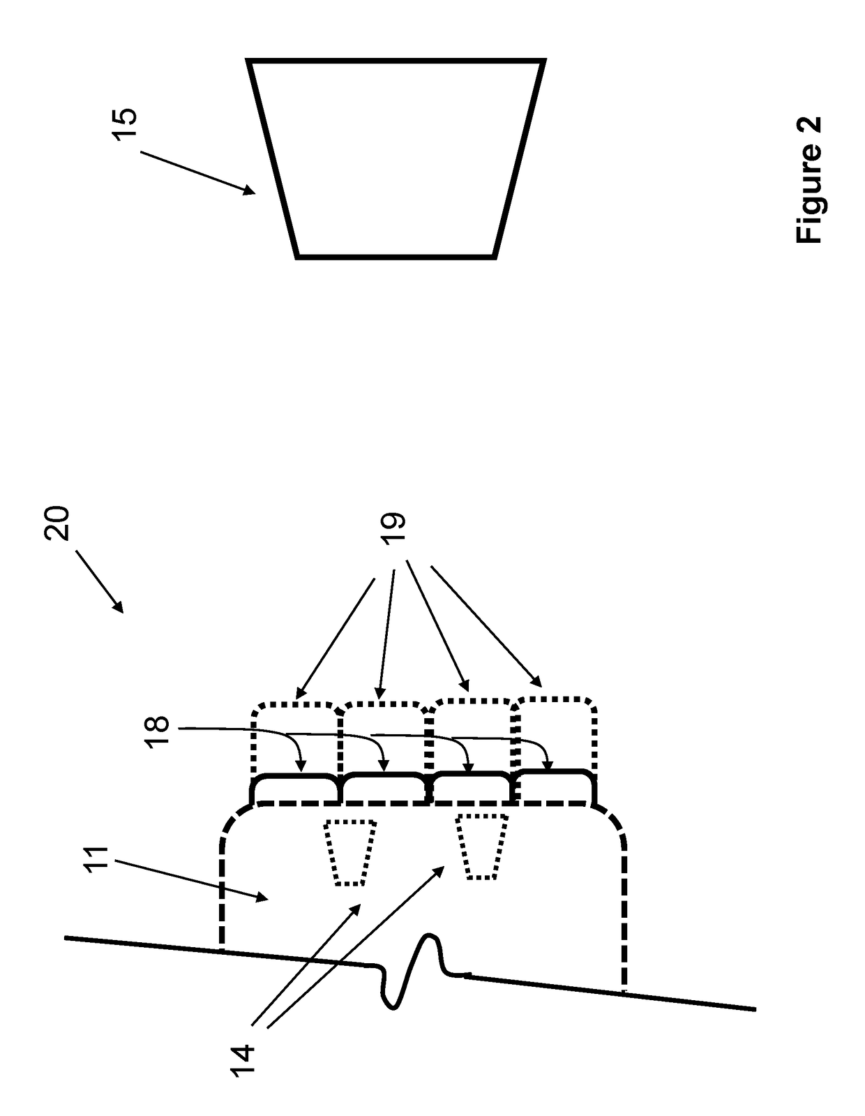
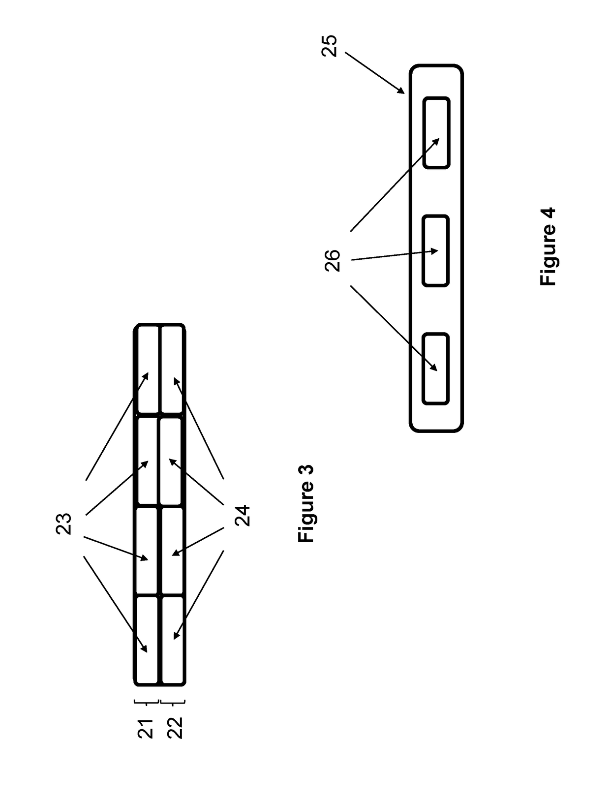
[0032]In the embodiment 20 shown in the schematic of FIG. 2, the deployable bumper 18 is shown to be constructed of several segments (four in FIG. 2) which can be independently deployed. It is, however, appreciated by those skilled in the art that the bumper may be similarly constructed with several rows of segments or in any other proper shapes and arrangements. The frontal view of one such deployable bumper that is constructed with two rows (indicated by numerals 21 and 22) of four segments (indicated by numerals 23 and 24 for the rows 21 and 22, respectively) is shown in FIG. 3. By providing several segmented deployable bumpers, each individual segment in each rows may be independently deployed to achieve maximum effectiveness. At low speeds and if only a small object is being encountered, the bumper deploying control unit will then also have the option of deploying any one or more of the required bumper segments.

[0033]In the embodiments of FIGS. 2 and 3, the deployable bumpers a...


PUM


Abstract

A system for protecting an automobile from a collision. The system including: a bumper having one or more bumper segments disposed on the automobile for absorbing at least some energy of the collision; and one or more actuators for deploying the bumper when conditions indicative of an impending collision is detected; wherein the one or more actuators comprise: one or more hydraulic actuators; one or more pneumatic actuators; one or more actuators actuated by one or more detonation charges; one or more fluid-filled bellows; one or more compressively pre-loaded springs; and one or more actuators connected to rotatable joints of links in a linkage.

Description

CROSS-REFERENCE TO RELATED APPLICATIONS[0001]This application claims the benefit of U.S. Provisional Application No. 62 / 548,368 filed on Aug. 21, 2018, the entire contents of which is incorporated herein by reference.[0002]This application is a continuation-in-part of U.S. application Ser. No. 14 / 991,973, filed on Jan. 10, 2016, the entire contents of which is incorporated herein by reference.BACKGROUND1. Field[0003]The present invention relates generally to vehicle bumpers, and more particularly to vehicle bumpers that are deployable when potential collision with an object is detected by the vehicle sensors to significantly increase the range of bumper deformation upon impact, thereby significantly reduce impact induced impulsive forces and increase energy absorption, thereby minimize passenger injury and damage to the vehicle.2. Prior Art[0004]Bumpers are used in motor vehicles to absorb low level impact forces and to limit the amount of damage sustained to the vehicle body during...

Claims


Application Information

Patent Timeline
IPC IPC(8): B60R19/40B60R21/0134B60R19/02
CPCB60R19/40B60R21/0134B60R19/023
Inventor RASTEGAR, JAHANGIR S.
Owner OMNITEK PARTNERS LLC
Why Eureka
Try Eureka