Emergency equipment for an aircraft comprising a respiratory mask

a technology of emergency equipment and respiratory mask, which is applied in the field of emergency equipment, can solve the problem that the opening size cannot be increased, and achieve the effect of easing the stowage of the respiratory mask

Inactive Publication Date: 2019-02-28
ZODIAC AEROTECHNICS
View PDF5 Cites 1 Cited by
  • Summary
  • Abstract
  • Description
  • Claims
  • Application Information

AI Technical Summary

Benefits of technology

The patent describes a device that helps users place a respiratory mask into a stowage device. The device has a movable main plate that is positioned by a support system. The main plate has features that help users correctly place the mask on the device. The technical effect of this invention is to make it easier and more convenient for users to place their masks in the stowage device, ensuring proper fitting and comfort during use.

Problems solved by technology

Because of all the other equipments which have also to be within arm's reach of the pilot, such a dedicated place is limited and the stowage device have to respect some dimensional features.
Therefore, the size of the opening cannot be increased.

Method used


Image

  • Emergency equipment for an aircraft comprising a respiratory mask
  • Emergency equipment for an aircraft comprising a respiratory mask
  • Emergency equipment for an aircraft comprising a respiratory mask

Examples


first embodiment

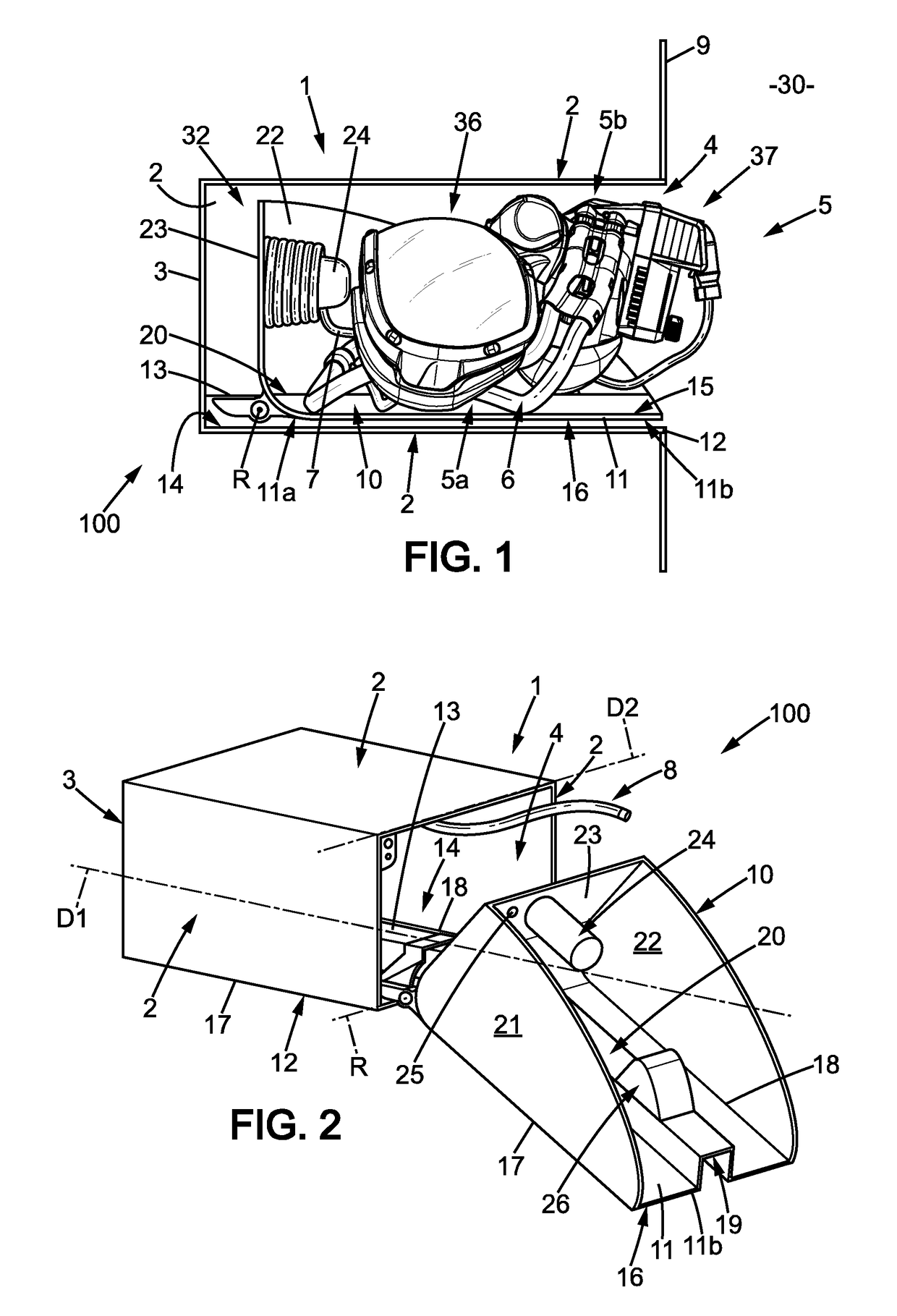
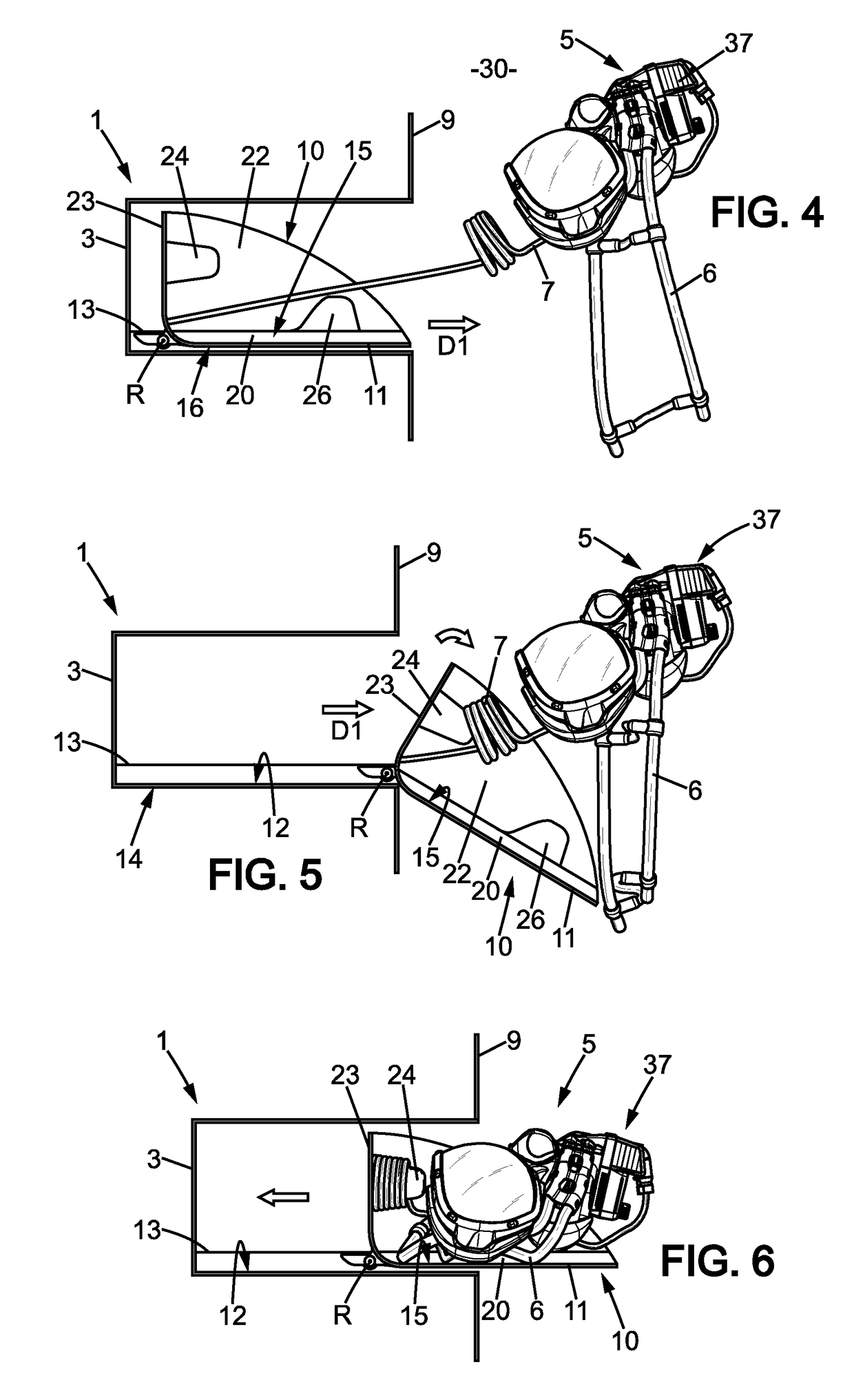
[0038]FIGS. 1 to 6 show an emergency equipment 100 according to the invention, the emergency equipment 100 being in a cabin 30 of an aircraft, in particular in the cockpit of the aircraft. The emergency equipment 100 comprises a respiratory mask 5, a stowage box 1 and a support 10.

[0039]The stowage box 1 stows the respiratory mask 5 in a stowage position of the emergency equipment 100 shown in FIG. 1.

[0040]The stowage box 1 comprises a housing having four side walls 2 forming a rectangular cross sectional tube (see more particularly FIG. 2) extending along a longitudinal direction D1, a back wall 3 closing one end of the rectangular cross sectional tube and an opening 4, opposite to the back wall 3, at the other end of the tube.

[0041]The housing comprises an internal space 32, delimited by the side walls 2 and the back wall 3. In a stowage position of the emergency equipment 100, the respiratory mask 5 is stowed in the internal space 32 (see FIGS. 1 and 4 to 6).

[0042]In the embodime...

second embodiment

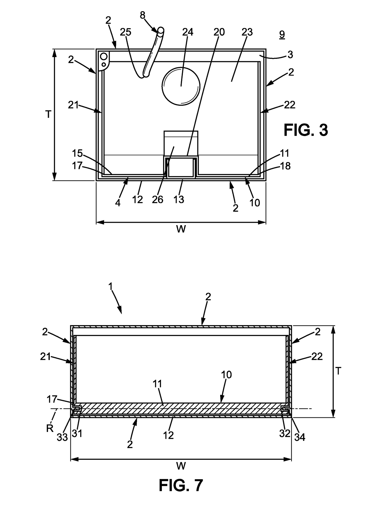
[0075]FIG. 7 shows a But it must be understood that the invention is not limited to the embodiments shown in figures and that other technical means could be used than the shown technical means without being out of the field of the invention.

[0076]FIG. 7 shows schematically the support 10 according to the invention, comprising a rigid plate 11, placed into the housing of a stowage box 1.

[0077]The rigid plate 11 comprises, along each of its longitudinal edges 17 and 18, a groove (respectively 31 and 32). Furthermore, in the embodiment shown, each lateral plate 21 and 22 of the housing comprises a sliding element 33 and 34 (respectively) proximate the opening 4, the sliding elements being formed by pins in the embodiment shown, each sliding element 33 and 34 sliding in the respective groove 31 and 32 when the support 10 slides between the backward position and the frontward position.

[0078]When the support 10 is in the frontward position, the support 10 is substantially outside the hous...


PUM


Abstract

An emergency equipment for an aircraft comprising: —a respiratory mask (5) comprising a harness (6), the respiratory mask (5) being adapted to be applied in a use position around the nose and the mouth of a user, —a stowage box (1) comprising a housing, the housing having side walls (2), a back wall (3) and an opening (4) opposite to the back wall (3), the side walls (2) and the back wall (3) defining an internal space (32) adapted to stow the respiratory mask (5) in a stowage position. The emergency equipment further comprises a support (10) supporting the respiratory mask (5) in the stowage position. The support (10) comprises a main plate (11) which is rigid and which is movable with respect to the stowage box (1) between a backward position and a frontward position along a longitudinal direction. The support (10) is in the backward position in the stowage position of the respiratory mask (5).

Description

FIELD OF THE DISCLOSURE[0001]The present invention relates to an emergency equipment to be used in an aircraft in particular by a crewmember.BACKGROUND OF THE DISCLOSURE[0002]Emergency equipments for aircraft comprising a respiratory mask and a stowage box are well known. The respiratory mask comprises an oronasal face piece and a harness. The oronasal face piece is intended to be applied on the face of the user in a use position to provide oxygen enriched respiratory gas. The harness enables to maintain the oronasal face piece on the face of the user. The respiratory mask may comprise a separate eye protective shield (goggles) or an eye protective shield integral with the oronasal face piece. The eye protective shield provides protection in particular against smoke and can also support a display device.[0003]The emergency equipments are placed in the cabin of an aircraft, in particular in the cabin of a commercial aircraft (not fighter aircraft), more particularly in the cockpit to...

Claims


Application Information

Patent Timeline
IPC IPC(8): B64D11/00A62B7/14A62B25/00
CPCB64D11/00A62B7/14A62B25/005B64D2231/025B64D10/00B64D11/0632A62B18/02
Inventor POTET, OLIVIERBOUCHET, BENO TBERTHET, FREDERIC
Owner ZODIAC AEROTECHNICS
Why Eureka
Try Eureka