Simple multi-sensor calibration

a multi-sensor and calibration technology, applied in the direction of instruments, process and machine control, vehicle position/course/altitude control, etc., can solve the problems of sensor, external and internal forces or errors, and require occasional calibration

Active Publication Date: 2019-04-18
SZ DJI TECH CO LTD
View PDF0 Cites 10 Cited by
  • Summary
  • Abstract
  • Description
  • Claims
  • Application Information

AI Technical Summary

Benefits of technology

[0003]According to some embodiments, a computer-implemented method is provided. The method comprises detecting, based on a first set of sensor data from a plurality of sensors coupled to an unmanned aerial vehicle (UAV), a change in a spatial configuration of the plurality of sensors from an initial spatial configuration to a subsequent spatial configuration; in response to detecting the change in the spatial con

Problems solved by technology

The sensors, susceptible to external and internal forces or errors, typically r

Method used


Image

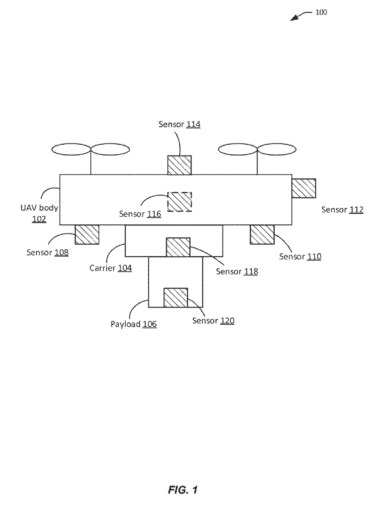
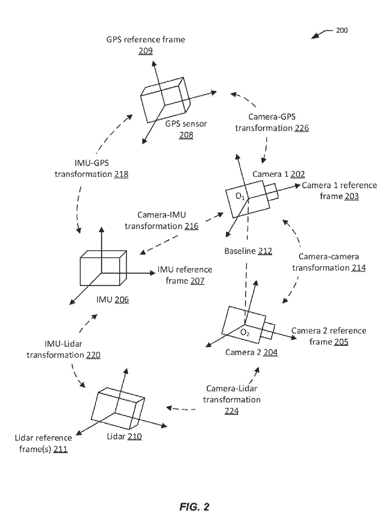
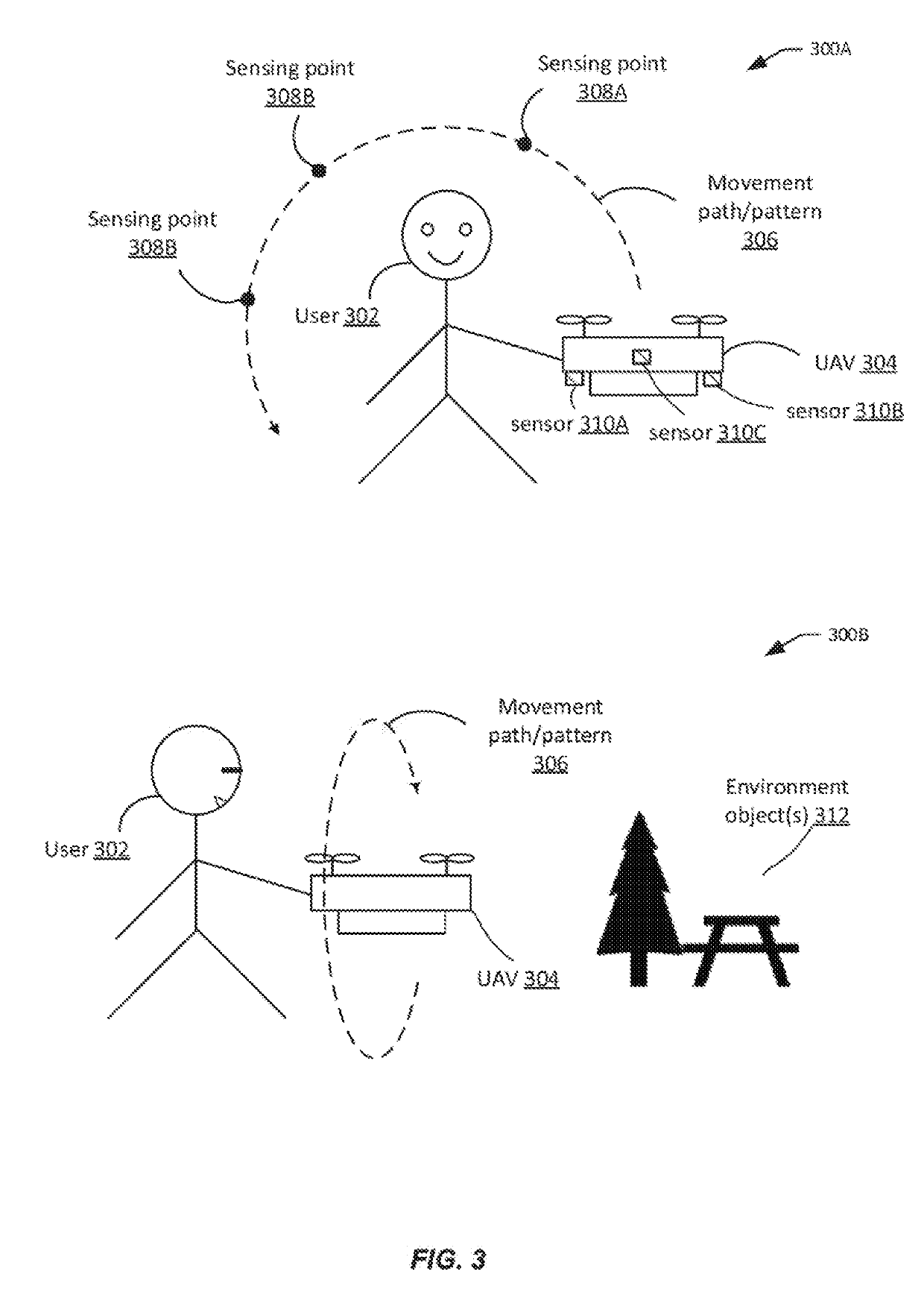
  • Simple multi-sensor calibration
  • Simple multi-sensor calibration
  • Simple multi-sensor calibration

Examples


Embodiment Construction

[0034]Conventional sensor calibration techniques usually require specialized calibration equipment and complex calibration procedures. For instance, traditional camera calibration typically requires the use of calibration boards with certain calibration pattern (e.g., checkerboard patterns), or a projection screen with such patterns. A camera captures images of the calibration pattern positioned at different poses so that the camera views the calibration pattern at different viewing planes. The images data is then processed to determine the intrinsic and extrinsic parameters of the camera. Such conventional calibration techniques suffer from several drawbacks. The calibration board may be costly, bulky, and not easily transportable to any location where sensor calibration is needed (e.g., in an outdoor environment). Positioning the calibration board at different poses to ensure that the camera captures the required information for calibration can be a time-consuming and tedious proc...


PUM


Abstract

A computer-implemented method includes detecting a change in a spatial configuration of a plurality of sensors coupled to an unmanned aerial vehicle (UAV) based on a first set of sensor data from a plurality of sensors, generating one or more calibration instructions to cause the UAV to move along a predetermined pattern in response to detecting the change in the spatial configuration, and determining a subsequent spatial configuration of the plurality of sensors based at least in part on a second set of sensor data from the plurality of sensors. The second set of sensor data is collected by the plurality of sensors when the UAV is moving along the predetermined pattern.

Description

CROSS-REFERENCE TO RELATED APPLICATION[0001]This application is a continuation of International Application No. PCT / CN2016 / 084753, filed on Jun. 3, 2016, the entire content of which is incorporated herein by reference.BACKGROUND OF THE DISCLOSURE[0002]Modern unmanned aerial vehicles (UAVs) are typically equipped with various sensors for collecting data used for performing a variety of tasks such as navigation, surveillance and tracking, remote sensing, search and rescue, scientific research, and the like. The sensors, susceptible to external and internal forces or errors, typically require occasional calibration to ensure precise and reliable collection of data.SUMMARY OF THE DISCLOSURE[0003]According to some embodiments, a computer-implemented method is provided. The method comprises detecting, based on a first set of sensor data from a plurality of sensors coupled to an unmanned aerial vehicle (UAV), a change in a spatial configuration of the plurality of sensors from an initial s...

Claims


Application Information

Patent Timeline
IPC IPC(8): G01P21/00G01C25/00B64C39/02G05D1/00G05D1/10
CPCG01P21/00G01C25/00B64C39/024G05D1/0011G05D1/101B64C2201/146G05D1/102G05D1/106B64U2201/20
Inventor ZHOU, YOUHAN, LEICAI, JIANZHAO
Owner SZ DJI TECH CO LTD
Why Eureka
Try Eureka