Sealant filled cable gland

a technology applied in the field of filling and filling cables, can solve problems such as packaging configuration bursting

Active Publication Date: 2019-04-18
THOMAS & BETTS INT INC
View PDF0 Cites 6 Cited by
  • Summary
  • Abstract
  • Description
  • Claims
  • Application Information

AI Technical Summary

Problems solved by technology

Further, the package is configured to rupture upon compression of the bushing body.

Method used


Image

  • Sealant filled cable gland
  • Sealant filled cable gland
  • Sealant filled cable gland

Examples


Embodiment Construction

[0022]Certain terminology is used in the foregoing description for convenience and is not intended to be limiting. Words such as “upper,”“lower,”“top,”“bottom,”“first,” and “second” designate directions in the drawings to which reference is made. This terminology includes the words specifically noted above, derivatives thereof, and words of similar import. Additionally, the words “a” and “one” are defined as including one or more of the referenced item unless specifically noted. The phrase “at least one of” followed by a list of two or more items, such as “A, B or C,” means any individual one of A, B or C, as well as any combination thereof.

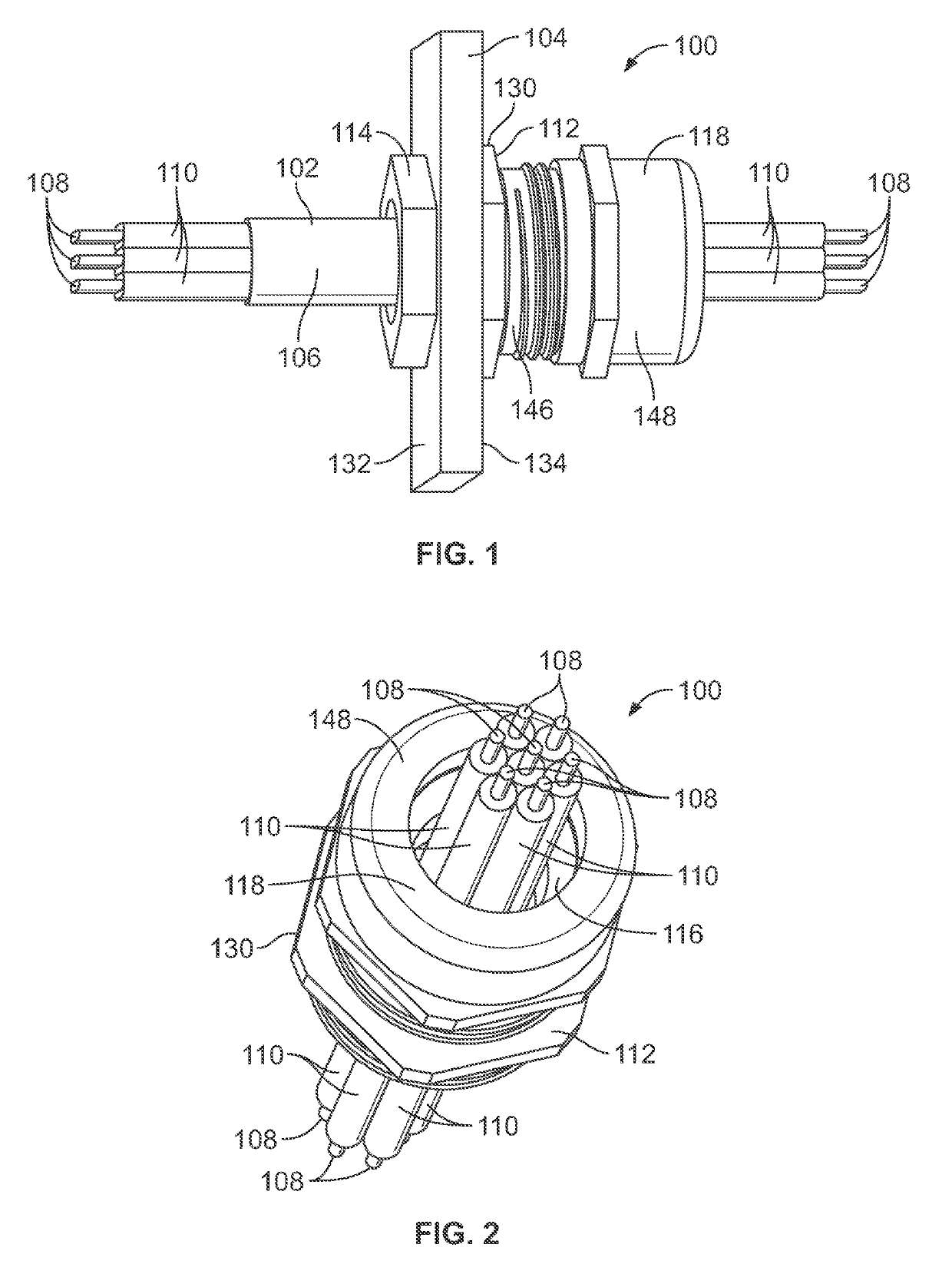
[0023]FIG. 1 illustrates a side perspective view of an exemplary cable gland 100 according to an illustrated embodiment of the subject application coupled to a portion, namely a wall 104, of a device. The cable gland 100 is configured to couple or secure one or more electrical cables or wires 102 (collectively referred to herein as “cable”) to a ...


PUM


Abstract

A cable gland for providing strain relief and sealing for a cable that can be coupled to a device. The cable gland includes a sealing gland having a sealant. Upon assembly of the cable gland, the sealing gland is compressed in a manner that can releases, or otherwise can facilitate the displacement of, the sealant about an interface between a portion of the cable and the sealing gland, and/or into spaces between exposed insulative jackets and/or conductors of the cable. The sealant can include a curable viscous sealant that is housed within a package of the sealing gland, the package being configured to rupture upon compression of the sealing gland. Alternatively, the sealant can be a malleable sealant material that can be pressed or otherwise displaced to form a seal between the sealing gland and cable and/or into the spaces between exposed insulative jackets and/or conductors of the cable.

Description

CROSS REFERENCE TO RELATED APPLICATIONS[0001]The present application claims the benefit of U.S. Provisional Patent Application Ser. No. 62 / 573,859, filed Oct. 18, 2017, which is incorporated herein by reference in its entirety.BACKGROUND[0002]Embodiments of the present application generally relate to cable glands. More particularly, but not exclusively, embodiments of the present application relate to cable glands that provide a sealant for protection of cables employed therein and the device to which the cable gland is attached.[0003]Cable glands can be used to provide strain relief for cables that are attached to structures or devices (collectively referred to herein as “devices”). More specifically, at least certain types of cable glands can be structured to be connected to both cables and devices in a manner that can at least assist in retaining a connection between the cable and the device, including assisting in preventing the cable from being pulled away, and / or being disconn...

Claims


Application Information

Patent Timeline
Patent Type & Authority Applications(United States)
IPC IPC(8): H02G15/04H02G15/007H02G15/013
CPCH02G15/04H02G15/007H02G15/013H02G3/0641H02G3/0675
Inventor PORTILLO GALLEGO, JESUS RICARDO
Owner THOMAS & BETTS INT INC
Why Eureka
Try Eureka