
Grinding wheel

Pending Publication Date: 2019-05-09
DISCO CORP
View PDF3 Cites 6 Cited by
  • Summary
  • Abstract
  • Description
  • Claims
  • Application Information

AI Technical Summary

Benefits of technology

The present invention is about a grinding wheel that can effectively discharge grinding water outside the segment grindstone, even when the grinding is extended. This prevents swarf from accumulating inside the grindstone, which could cause scratches on the device being ground. The grinding wheel has slits in the base that function as discharge ports, allowing swarf to flow out and avoid stagnating inside the grindstone. This results in a cleaner surface and better quality device production.

Problems solved by technology

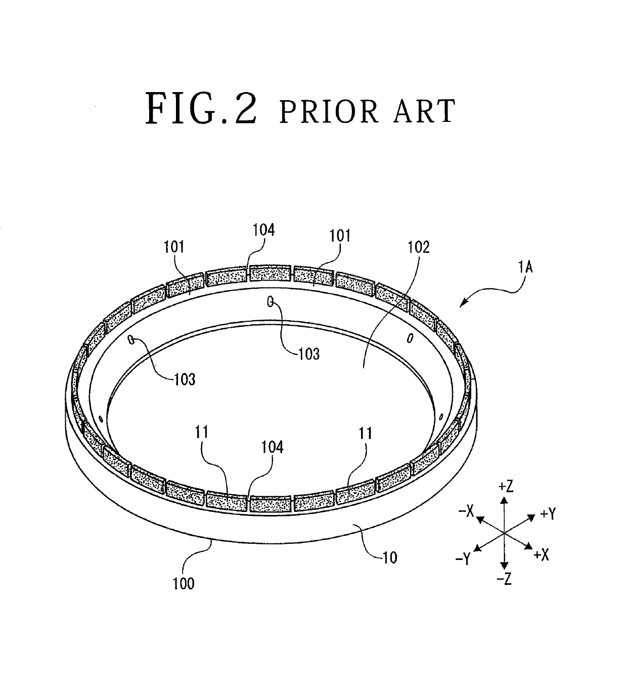
As the segment grindstone is worn down toward a root thereof by grinding, however, the segment grindstone, now lower in height, diminishes the gap (discharge port), resulting a reduced draining effect.
This unfortunately affects a device.

Method used


Image

  • Grinding wheel
  • Grinding wheel
  • Grinding wheel

Examples


Embodiment Construction

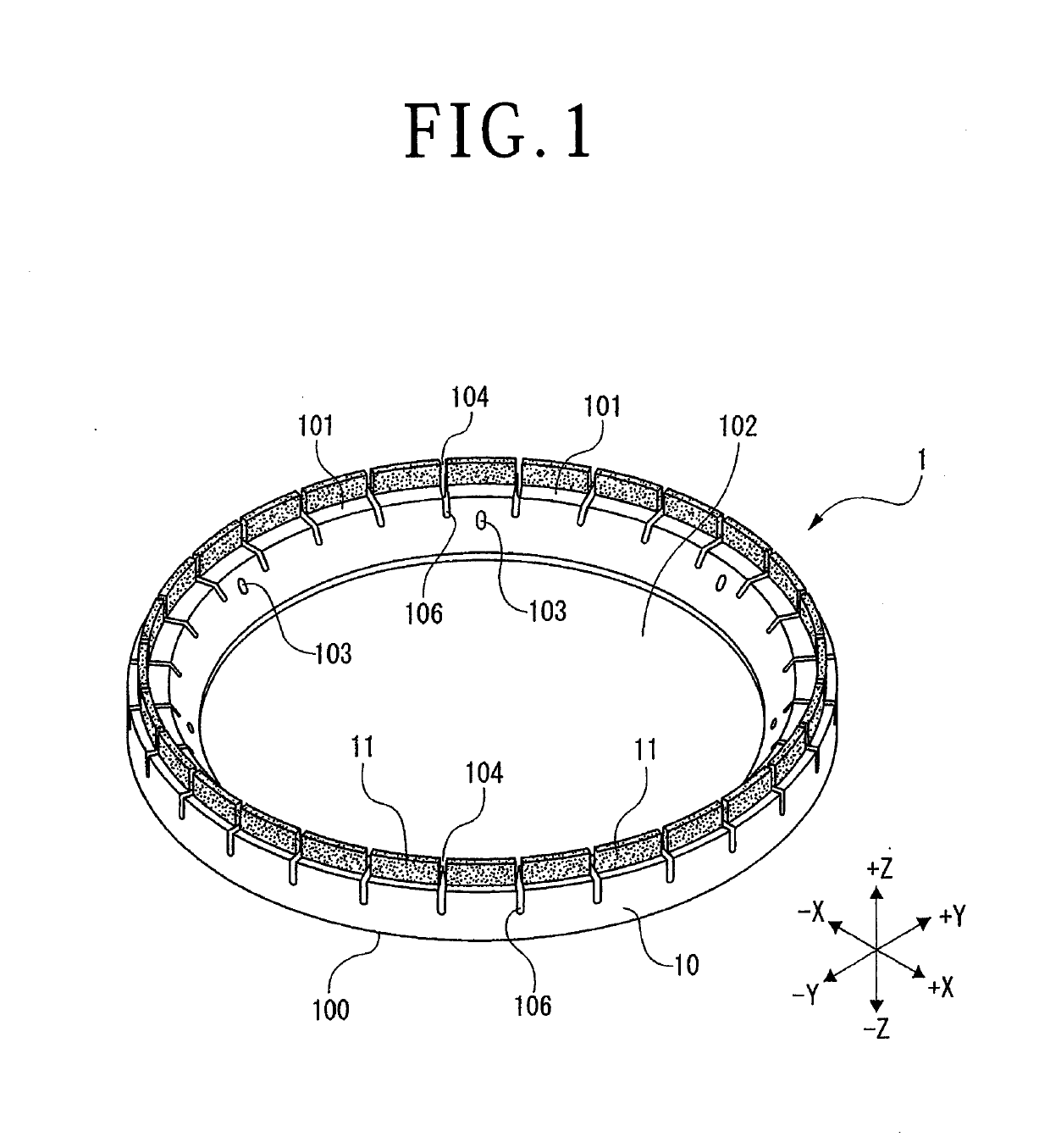
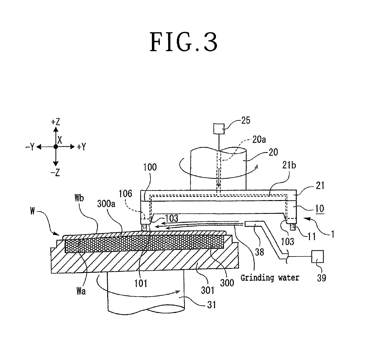
[0013]A grinding wheel 1 according to an embodiment of the present invention depicted in FIGS. 1 and 3 includes a ring-shaped base 10 formed of, for example, stainless steel or aluminum. The base 10 has a flat mounting surface 100. The mounting surface 100 is mounted on a side of a distal end of a spindle 20 depicted in FIG. 3 via a wheel mount 21 depicted in FIG. 3. A surface of the base 10 opposite to the mounting surface 100 assumes a flat grindstone fixing surface 101. A segment grindstone is fixed to the grindstone fixing surface 101. The mounting surface 100 and the grindstone fixing surface 101 extend in parallel with each other. As depicted in FIG. 1, the base 10 has a circular opening 102 formed at a center thereof. The opening 102 passes through the base 10, extending from the mounting surface 100 to the grindstone fixing surface 101.

[0014]A plurality of segment grindstones 11 are fixedly attached annularly to the grindstone fixing surface 101 of the base 10 by an appropri...


PUM


Abstract

A grinding wheel is mounted at a distal end of a spindle and grinds a wafer held on a holding table. The grinding wheel includes: an annular base having a mounting surface to be mounted on the distal end of the spindle; and a plurality of segment grindstones that are fixedly attached annularly to a surface opposite to the mounting surface of the annular base and that are equidistantly spaced apart from each other. The annular base has a plurality of slits formed therein. Each of the slits represents a gap that is formed between two adjacent segment grindstones and that is extended toward a side of the annular base such that the slit has a width of the gap.

Description

BACKGROUND OF THE INVENTIONField of the Invention[0001]The present invention relates to a grinding wheel that grinds a plate-shaped workpiece such as a wafer.Description of the Related Art[0002]In performing a grinding operation for grinding a wafer, a grinding apparatus (see, for example, Japanese Patent Laid-Open No. 2000-288881) that includes a holding table and a grinding unit is used. The holding table holds the wafer. The grinding unit includes a spindle that rotates a wheel mount in which a grinding wheel is mounted. The grinding wheel includes a plurality of segment grindstones disposed annularly therein. Then grinding is performed as follows. While grinding water is supplied to the segment grindstones, a rotating grinding wheel is lowered to thereby bring the segment grindstones into contact with an upper surface of the wafer held in the holding table.SUMMARY OF THE INVENTION[0003]A predetermined spacing (gap) is provided between two adjacent segment grindstones, so that th...

Claims


Application Information

Patent Timeline
IPC IPC(8): B24D7/06B24B7/22B24B41/047B24B41/00B24B55/02
CPCB24D7/06B24B7/228B24B41/047B24B41/002B24B55/02
Inventor TATEISHI, TOSHIYUKI
Owner DISCO CORP
Learn More