
Image Forming Apparatus and Method of Controlling the Same

a technology of forming apparatus and forming apparatus, which is applied in the direction of electrographic process apparatus, instruments, optics, etc., can solve the problem of error in the supply amount of the developer and the consumption amount of the developer

Active Publication Date: 2019-05-23
BROTHER KOGYO KK
View PDF0 Cites 5 Cited by
  • Summary
  • Abstract
  • Description
  • Claims
  • Application Information

AI Technical Summary

Benefits of technology

The disclosure "technical effect" is about preventing mistakes in the amount of developer supplied by avoiding it from getting in the way and stopping it from accumulating.

Problems solved by technology

In such a case, the staying or accumulating developer hinders conveyance of the developer, undesirably causing an error in the supply amount of the developer with respect to the consumption amount of the developer.

Method used


Image

  • Image Forming Apparatus and Method of Controlling the Same
  • Image Forming Apparatus and Method of Controlling the Same
  • Image Forming Apparatus and Method of Controlling the Same

Examples


Embodiment Construction

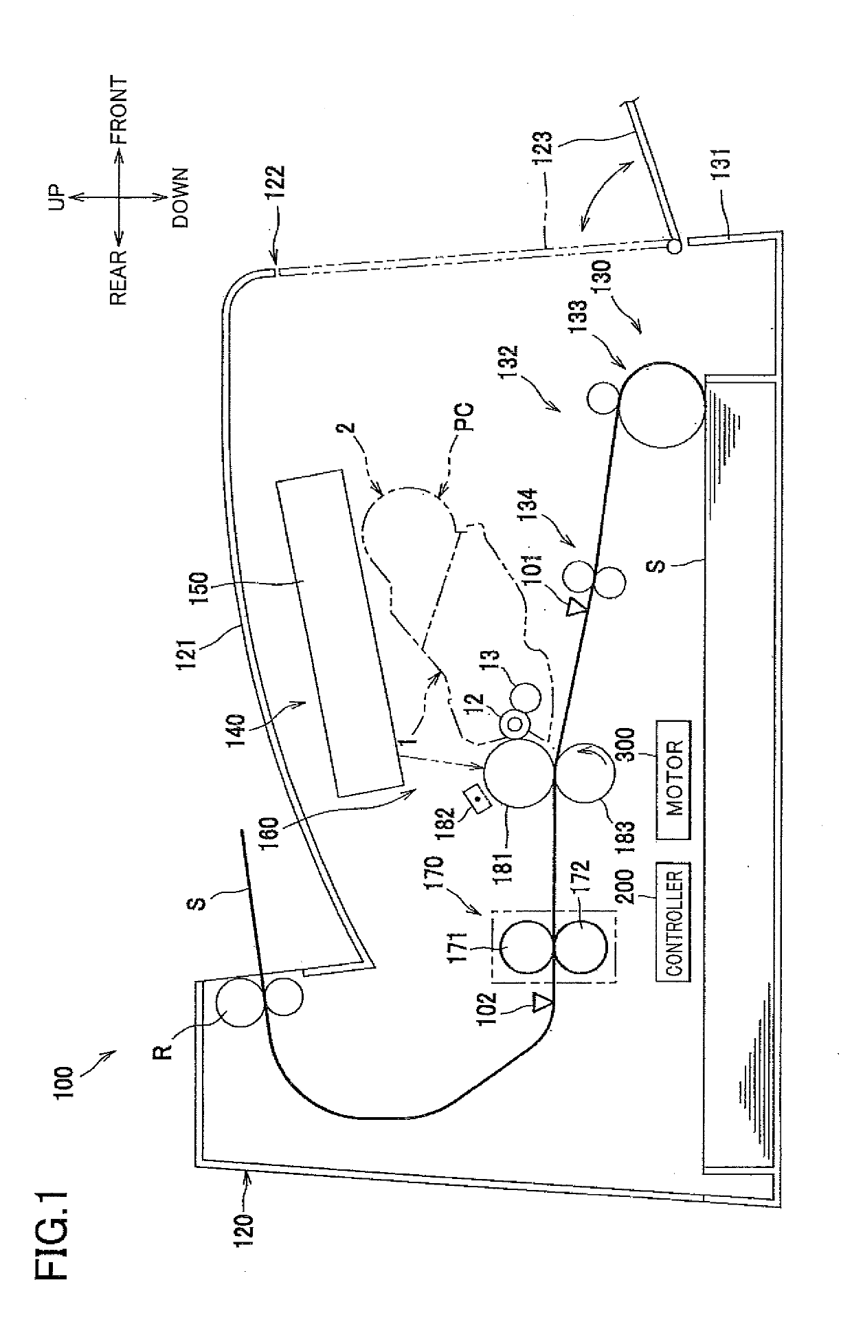
[0026]There will be next explained in detail one embodiment of the present disclosure referring to the drawings. In the following explanation, directions are defined based on directions indicated in FIG. 1. That is, a right side and a left side in FIG. 1 are respectively defined as a front side and a rear side, and a side corresponding to a back surface of the sheet of FIG. 1 and a side corresponding to a front surface of the sheet of FIG. 1 are respectively defined as a right side and a left side. Further, an up-down direction in FIG. 1 is defined as an up-down direction.

[0027]As shown in FIG. 1, a laser printer 100 as one example of an image forming apparatus includes, in a printer housing 120, a feeder portion 130 configured to supply a sheet S, an image forming portion 140 configured to form an image on the sheet S, a controller 200, and a motor 300. A drive force of the motor 300 is transmitted to the feeder portion 130 and the image forming portion 140.

[0028]The feeder portion...


PUM


Abstract

An image forming apparatus, including: a photoconductor; a developing device; a developer storage; a supplier configured to supply developer to the developing device; and a controller configured to, when performing a printing operation, execute a developing process, a usage-amount obtaining process of obtaining a developer usage amount used in the developing process, a first supplying process of supplying the developer by operating the supplier by a first driving amount every time the usage amount becomes greater than or equal to a first threshold, and a second supplying process of supplying the developer by operating the supplier by a driving amount greater than the first driving amount when the usage amount from a time point of beginning of use of the developer storage becomes greater than or equal to a second threshold that is greater than the first threshold.

Description

CROSS REFERENCE TO RELATED APPLICATION[0001]The present application claims priority from Japanese Patent Application No. 2017-225145, which was filed on Nov. 22, 2017, the disclosure of which is herein incorporated by reference in its entirety.BACKGROUNDTechnical Field[0002]The following disclosure relates to an image forming apparatus including a supplier configured to supply developer from a developer storage to a developing device and also relates to a method of controlling the image forming apparatus.Description of Related Art[0003]There has been known a printer configured to supply, as needed, new or fresh developer from a developer storage to a developing device configured to supply the developer to a photoconductor. In the known printer, an amount of consumption of the developer is calculated based on a dot count, and the developer is supplied to the developing device based on the calculated consumption amount, so as to keep the amount of the developer in the developing devic...

Claims


Application Information

Patent Timeline
Patent Type & Authority Applications(United States)
IPC IPC(8): G03G15/08
CPCG03G15/0856G03G15/0889G03G15/556
Inventor HINOUE, KAZUMAHAYASHI, RYOSUKESHIMIZU, TAKASHISUZUKI
Owner BROTHER KOGYO KK
Learn More